Rolling wheel type intelligent rail flaw detection method based on optical-electro-mechanical-hydraulic integration

A rail flaw detection vehicle and roller type technology, applied in the direction of optical testing flaws/defects, etc., can solve the problems of damage, efficient and continuous detection of rails, etc., achieve high measurement accuracy, improve standstill operation methods, and reduce costs.

Inactive Publication Date: 2015-03-04
EAST CHINA JIAOTONG UNIVERSITY
View PDF5 Cites 0 Cited by
  • Summary
  • Abstract
  • Description
  • Claims
  • Application Information

AI Technical Summary

Problems solved by technology

[0004] The technical solution adopted by the present invention to solve the technical problem is: in order to overcome the deficiency that the existing traditional flaw detection equipment cannot efficiently and continuously detect rail damage on site, the principle of the present invention is that when the flaw detection vehicle moves at a certain speed on the rail, The rollers equipped with probes rotate at a given speed in the opposite direction to the running speed of the flaw detection vehicle. There are three rollers on both sides of the flaw detection vehicle, and each roller is equipped with a probe. The difference between the probes on adjacent rollers is 120 degrees. The speed of the roller relative to the flaw detection vehicle can obtain higher detection speed and efficiency

Method used


Image

  • Rolling wheel type intelligent rail flaw detection method based on optical-electro-mechanical-hydraulic integration
  • Rolling wheel type intelligent rail flaw detection method based on optical-electro-mechanical-hydraulic integration
  • Rolling wheel type intelligent rail flaw detection method based on optical-electro-mechanical-hydraulic integration

Examples


Embodiment 1

[0017] Embodiment 1. A method for intelligent flaw detection of roller-type rails based on electromechanical-optical-liquid integration,

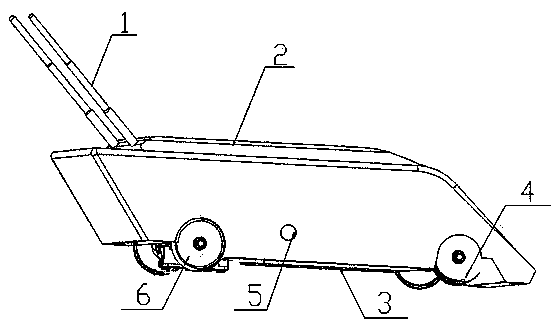
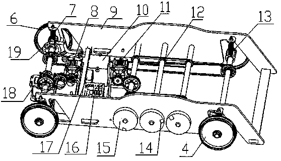
[0018] It consists of front and rear wheels, frame, motor, gearbox, sensor, probe, brake disc, hydraulic pump, and power supply; among them: two rear wheels (6) and gearbox (18) are installed on the rear axle, and the gearbox Among them, the top end cover is connected to the upper end cover through the top bolts, there are two pairs of gears in the gearbox, two-stage speed change, the motor Ι (8) is suspended on the beam through the motor hanger on the frame, and the power supply (10) is fixed on the On the vehicle frame bottom plate, the rear shock absorber (7) is connected with the rear axle through the lower end, and the upper end is connected with the vehicle frame.

Embodiment 2

[0019] Embodiment 2. A roller-type rail intelligent flaw detection method based on electromechanical-optical-liquid integration, wherein: the gravity sensor (5) is installed on the shell (2) of the flaw detection vehicle to check whether the flaw detection vehicle is running smoothly, and the front wheels (4 ), the front shock absorber (13) forms the guiding system by the front axle.

Embodiment 3

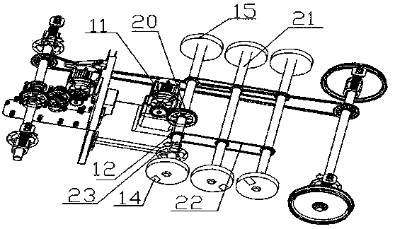
[0020] Embodiment 3. A roller-type rail intelligent flaw detection method based on electromechanical-optical-liquid integration, wherein: the flaw detection equipment is composed of a roller (15), a roller (21) and a probe (14), and is installed on both sides of the flaw detection vehicle. There are three rollers, each roller is equipped with a probe, and the difference between the probes on adjacent rollers is 120 degrees. Using the speed of the rollers relative to the flaw detection vehicle can obtain higher detection speed and efficiency. The flaw detection probe on the roller will emit laser light to the rail at a certain speed to detect the damage inside.


PUM


Abstract

The invention discloses a rolling wheel type intelligent rail flaw detection method based on optical-electro-mechanical-hydraulic integration. The technical scheme is as follows: when a flaw detection vehicle runs on rails at a certain speed, rolling wheels provided with probes rotate in the direction opposite to the running direction of the flaw detection vehicle at a given speed, three rolling wheels are mounted on each of two sides of the flaw detection vehicle, one probe is mounted on each rolling wheel, the angle formed by the probes on every two rolling wheels is 120 degrees, and the higher detection speed and efficiency can be obtained by the aid of the speed of the rolling wheels relative to the flaw detection vehicle. The probes has photo-thermal modulation and wireless transmission functions, the probes can emit lasers when moving above the rails, the lasers irradiate into the rails to emit heat, and the heat enables flaws (such as blind cracks) in the rails to be closed, so that excited surface wave signals produce obvious peek variation wirelessly transmitted to a control system on the vehicle, and positions and shapes of the flaws of the rails can be further determined.

Description

technical field [0001] The invention relates to a new method for detecting the damage of steel rails in service. Background technique [0002] Rail flaw detection vehicle (hereinafter referred to as flaw detection vehicle) has already replaced manual flaw detection equipment in developed countries abroad, and has become the main means of detecting rail damage in service. Due to the advantages of high sensitivity, fast detection speed and accurate positioning of ultrasonic detection of rail fatigue cracks and other internal defects, domestic and foreign flaw detection vehicles have adopted ultrasonic flaw detection technology for internal crack detection, which is limited by the detection mode and ultrasonic technology. The speed is generally 10~70 km / h. Most of the flaw detection vehicles in North America adopt the stop operation method, that is, after the flaw detection vehicle discovers suspicious damage, it needs to stop and have the operator of the flaw detection vehicl...

Claims


Application Information

Patent Timeline
Patent Type & Authority Applications(China)
IPC IPC(8): G01N21/88
Inventor 肖乾杨逸航方骏邱国荣
Owner EAST CHINA JIAOTONG UNIVERSITY
Why Eureka
Try Eureka