Light leaking prevention liquid crystal display

A liquid crystal display, anti-light leakage technology, applied in the fields of instruments, optics, nonlinear optics, etc., can solve the problems of increasing production processes, difficult combination of backplane and plastic frame, affecting product quality, etc., to avoid light leakage, reasonable design, simple structure

Active Publication Date: 2015-03-04
L&T DISPLAY TECH FUJIAN
View PDF5 Cites 14 Cited by
  • Summary
  • Abstract
  • Description
  • Claims
  • Application Information

AI Technical Summary

Problems solved by technology

[0004] 1) If the light-shielding tape is pasted at each gap where the light path penetrates, it will destroy the appearance of the display back panel
[0005] 2) If an adhesive strip is installed at the matching gap formed between the backplane and the plastic frame, in order to block the light from passing through, but the thickness of the adhesive strip is difficult to control, because the gap between the backplane and the plastic frame is usually only 0.1 mm, the adhesive strip is too thin to achieve a blocking effect, and the adhesive strip is too thick to cause extrusion of the backplane and the rubber frame, making it difficult to combine the backplane and the rubber frame, and the setting of the adhesive strip needs to increase the production process, and it is easy to contaminate the backplane. Optical film in the board, affecting product quality
[0006] 3) If the extension of the middle frame is added at the bottom of the middle frame to cover the bottom surface of the backplane, so that it covers the light outlet of the matching gap, although this design can block the transmission of light, the extension of the middle frame increases the thickness of the display (like figure 2 shown), which affects the ultra-thin effect of the display

Method used


Image

  • Light leaking prevention liquid crystal display
  • Light leaking prevention liquid crystal display
  • Light leaking prevention liquid crystal display

Examples


Embodiment Construction

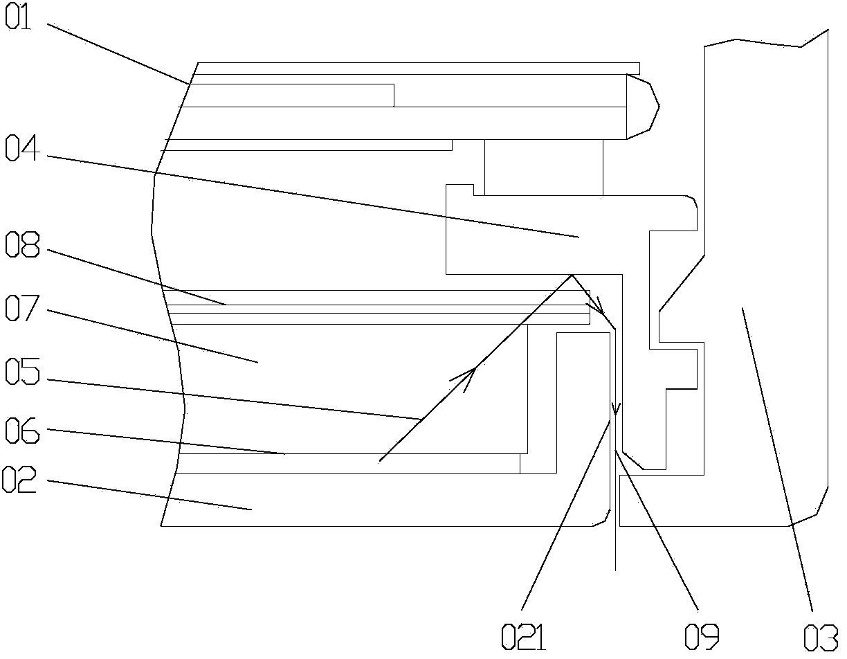
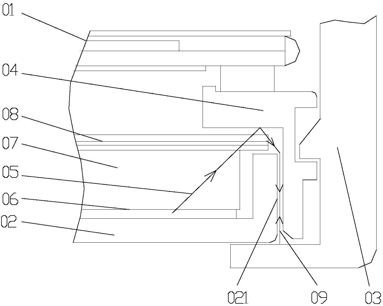
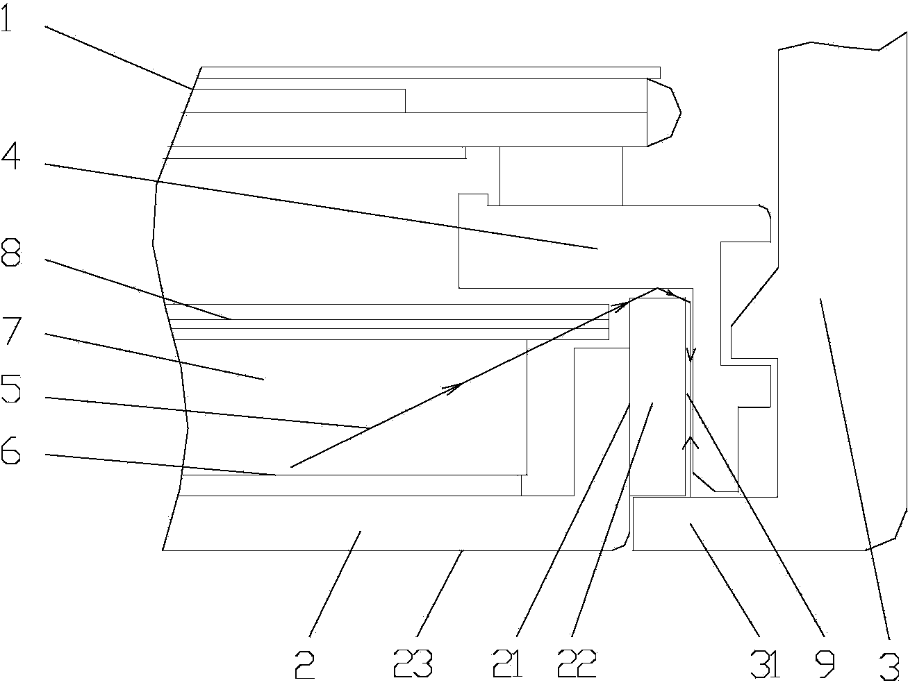
[0018] Such as image 3 As shown, the present invention includes a liquid crystal panel 1, a back plate 2, a middle frame 3 and a plastic frame 4. The back plate 2 is concave, and the back plate 2 is provided with a reflective sheet 6 and a guide in order from bottom to top. The light plate 7 and the optical film 8, the liquid crystal panel 1 is arranged above the optical film 8, the middle frame 3 is arranged outside the side 21 of the back plate, the plastic frame 4 is T-shaped, and the plastic frame 4 is arranged on Between the liquid crystal panel 1, the optical film 8, the side surface 21 of the back plate and the middle frame 3, the side surface 21 of the back plate is provided with a bending part 22, and the bottom end of the middle frame 3 is provided with an extension part 31, and the folding part The vertical distance between the end of the bent portion 22 corresponding to the bottom surface of the back plate 23 and the bottom surface 23 of the back plate is equal to ...


PUM


Abstract

The invention relates to the field of liquid crystal display, in particular to a light leaking prevention liquid crystal display which comprises a liquid crystal panel, a back plate, a middle frame and a rubber frame, wherein the back plate is concave; a reflection piece, a light guide plate and an optical membrane piece are sequentially arranged from bottom to top inside the back plate; the liquid crystal panel is arranged above the optical membrane piece; the middle frame is arranged outside the side surface of the back plate; the rubber frame is T-shaped and is arranged among the liquid crystal panel, the optical membrane piece, the side surface of the back plate and the middle frame; a bent part is arranged outside the side surface of the back plate; an extension part is arranged at the bottom of the middle frame; the vertical distance between one end corresponding to the bottom side of the back plate, of the bent part, and the bottom side of the back plate is equal to the thickness of the extension part; the bent part and the rubber frame are both positioned in an accommodation cavity formed among the back plate, the middle frame and the extension part of middle frame; the bent part and the back plate are integrally formed in a punched manner; the other end of the bent part is higher than the side surface of the back plate; the sum of the thicknesses of the rubber frame and the bent part is equal to the length of the extension part.

Description

Technical field [0001] The present invention relates to the technical field of liquid crystal displays, in particular to a light-leakage liquid crystal display. technical background [0002] The existing frameless liquid crystal display is generally composed of a liquid crystal display module, a middle frame, and a rear case. The liquid crystal display module includes a liquid crystal panel, a plastic frame, an optical film, a light guide plate, a light source, and a back plate. In the existing structural design schemes of ultra-thin liquid crystal displays, in order to enhance the heat dissipation of the liquid crystal display and reduce the thickness of the liquid crystal display at the same time, there is a design scheme that directly exposes the back plate and cancels the back shell at the same time, that is, replace the back shell with the back plate In this way, not only can the material for the rear case be omitted, and the process of rear case assembly can be reduced, but...

Claims


Application Information

Patent Timeline
Patent Type & Authority Applications(China)
IPC IPC(8): G02F1/13357
CPCG02F1/133308G02F1/133314G02F1/133317
Inventor 叶小春念明
Owner L&T DISPLAY TECH FUJIAN
Why Eureka
Try Eureka