A fluorescent excitation device, projection light source and projection equipment

A technology for fluorescence excitation and excitation light source, which is applied in the direction of projection devices, optics, optical components, etc., can solve the problems of uneven fluorescence excitation spots, uneven fluorescence, light loss, etc., so as to improve the uneven distribution of fluorescent spots and reduce the intensity Contrast, collection efficiency improvement effect

Active Publication Date: 2018-08-24
QINGDAO HISENSE LASER DISPLAY CO LTD
View PDF25 Cites 0 Cited by
  • Summary
  • Abstract
  • Description
  • Claims
  • Application Information

AI Technical Summary

Problems solved by technology

[0006] either in the above Figure 1A or Figure 1B In the illumination mode shown, on the one hand, due to the difference in convergence speed between the fast axis and the slow axis of the laser BANK itself, the laser spot itself has certain inhomogeneity, and when using such as Figure 1B In the way shown, especially when the laser is transmitted through the lens group composed of multiple lenses, due to the lens processing technology, the accumulation of aberrations of the multiple lenses, and the lens being irradiated by the laser spot with high energy density, a temperature gradient is generated by itself. Poor, so that the refractive index of the lens also changes, these reasons will again aggravate the unevenness of the laser spot
When the uneven laser spot is irradiated on the phosphor, it will inevitably lead to the unevenness of the stimulated fluorescence.
[0007] and, in Figure 1A and 1B In the method shown, due to the wide range of divergence angles of fluorescence, even if the lens for collecting light is placed closer to the rotating fluorescent wheel, the light beams with large divergence angles are still unavoidable and cannot be collected by the lens, resulting in light loss and resulting in fluorescence The collection efficiency is also low
[0008] To sum up, in the current fluorescence excitation lighting method, there are technical defects in the unevenness of the fluorescence excitation spot and low light collection efficiency.

Method used


Image

  • A fluorescent excitation device, projection light source and projection equipment
  • A fluorescent excitation device, projection light source and projection equipment
  • A fluorescent excitation device, projection light source and projection equipment

Examples


Embodiment 1

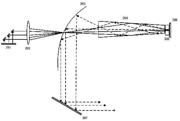
[0055] see Figure 2A , is a schematic diagram of the optical architecture of a fluorescence excitation device provided by an embodiment of the present invention.

[0056] Such as Figure 2A As shown, the optical architecture of the fluorescence excitation device includes:

[0057] The excitation light source 201 may be a blue laser or an ultraviolet laser in a specific embodiment, and a blue laser is taken as an example in this example.

[0058] The reflective concentrating device 203 may be a parabolic reflective bowl in a specific implementation, wherein the concave surface of the paraboloid is coated with a high-reflection film, which is a reflective surface, a light guide 204 , a fluorescent crystal 205 , and a reflective component 206 . And, because the light-through hole of the reflection-type concentrating device 203 is usually set to a certain size in order to reduce the escape of reflected light, that is, to reduce the loss of fluorescent reflected light, the openi...

Embodiment 2

[0085] Such as Figure 2C shown, based on Figure 2B The fluorescence excitation device provides a schematic diagram of the optical structure of the projection light source. For the description of the fluorescence excitation device, please refer to the content of Embodiment 1, which will not be repeated here.

[0086] In this example, the fluorescent crystal 205 is fixedly arranged between the light guide 204 and the reflective member 206, and the fluorescent crystal 205 is excited by the light beam transmitted by the reflective concentrating device 203 to generate fluorescence of the first color. The projection light source also includes: The second laser light source 210 is specifically a blue laser, the third laser light source 211 is specifically a red laser, and a first dichroic mirror 209a and a second dichroic mirror 209b.

[0087] Wherein, the first dichroic mirror 209 a transmits the green fluorescent light reflected from the deformable mirror 207 and reflects the la...

Embodiment 3

[0092] see Figure 5 , based on Figure 2B A schematic diagram of the optical architecture of another projection light source is provided. Figure 5 A schematic diagram of the optical architecture is shown with Figure 2B The architecture diagram shown is similar, except that the placement of the red and blue lasers is different, Figure 5 The transmission path of the light beam and the Figure 2B The architecture diagram shown is the same, and no specific description is made here. For details, please refer to the above-mentioned Figure 2B specific description.

[0093] Figure 5 Figure 1 shows the optical architecture of the projected light source, compared to Figure 2B , the dichroic mirror 209 , the blue laser 210 and the red laser 211 are arranged in the incident light path of the deformable mirror 207 . The dichroic mirror 209 transmits the green fluorescent light reflected from the reflective concentrating device 203 to the deformable reflector 207, and reflects...


PUM


Abstract

The invention discloses a fluorescence excitation device comprising a laser light source used for emitting a laser light beam; the laser light beam penetrates a reflective optically focused unit and enters to a fluorescence crystal through a photoconductive tube, thus exciting the fluorescence crystal to illuminate; the fluorescence emitted by the fluorescence crystal is reflected to the reflective optically focused unit through a reflection part, and collimated and reflected to a deformation reflector; the deformation reflector is controlled by a drive part so as to have surface formation, thus diversifying transmission angles of the reflected light beam, and uniforming the light beam light spot distribution. The invention also discloses the projection light source and projection equipment.

Description

technical field [0001] The invention relates to the field of light beam illumination, in particular to a fluorescent excitation device, a projection light source and projection equipment. Background technique [0002] At present, there are mainly two ways to provide light source lighting in the industry: Figure 1A The schematic diagram of the architecture shown includes 01 laser BANK, and the parallel or nearly parallel laser emitted by 02 reflective bowl is reflected and converged to the surface of 03 fluorescent wheel to excite the fluorescent material. In this schematic diagram, the 03 fluorescent wheel is a transmissive fluorescent wheel, and the excited fluorescence is emitted from the back of the 03 fluorescent wheel, and then emitted after being converged by the 04 collimating lens group. Figure 1A What is shown is to provide illumination by collecting laser light through the reflective bowl and illuminating the rotating fluorescent wheel. In this way, due to the sur...

Claims


Application Information

Patent Timeline
Patent Type & Authority Patents(China)
IPC IPC(8): G03B21/20G02B26/00
CPCG02B26/008G03B21/204G03B21/2066
Inventor 郭汝海刘显荣田有良
Owner QINGDAO HISENSE LASER DISPLAY CO LTD
Why Eureka
Try Eureka