A fluorescent excitation device, projection light source and projection equipment
A technology of fluorescence excitation and excitation light source, which is applied in the direction of projection devices, optics, instruments, etc., can solve the problems of uneven laser spot, low light collection efficiency, uneven fluorescence, etc., and achieve uniform energy distribution of spot and uniform energy distribution of beam , Reduce the effect of strong and weak contrast
- Summary
- Abstract
- Description
- Claims
- Application Information
AI Technical Summary
Problems solved by technology
Method used
Image
Examples
Embodiment 1
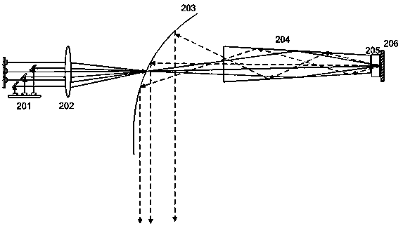
[0051] see Figure 2A , is a schematic diagram of the optical architecture of a fluorescence excitation device provided by an embodiment of the present invention.
[0052] Such as Figure 2A As shown, the optical architecture of the fluorescence excitation device includes:
[0053] The excitation light source 201 may be a blue laser or an ultraviolet laser in a specific embodiment, and a blue laser is taken as an example in this example.
[0054] The reflective concentrating device 203 may be a parabolic reflective bowl in a specific implementation, wherein the concave surface of the paraboloid is coated with a high-reflection film, which is a reflective surface, a light guide 204, a fluorescent crystal 205, and a deformable reflector 206. And, because the light-through hole of the reflection-type concentrating device 203 is usually set to a certain size in order to reduce the escape of reflected light, that is, to reduce the loss of fluorescent reflected light, the opening ...
Embodiment 2
[0080] Such as Figure 2C shown, based on Figure 2B The fluorescence excitation device provides a schematic diagram of the optical structure of the projection light source. For the description of the fluorescence excitation device, please refer to the content of Embodiment 1, which will not be repeated here.
[0081] exist Figure 2C In the schematic diagram of the projection light source architecture shown, the fluorescent crystal 205 is fixedly arranged between the light guide 204 and the deformable mirror 206, and the fluorescent crystal 205 is excited by the light beam transmitted by the reflective concentrating device 203 to generate fluorescence of the first color. The light source further includes: a second laser light source 210, specifically a blue laser, a third laser light source 211, specifically a red laser, and a first dichroic mirror 209a and a second dichroic mirror 209b.
[0082] Specifically, in Figure 2B On the basis of the provided architecture, a dich...
Embodiment 3
[0093] see Figure 5 , based on Figure 2C A schematic diagram of the optical architecture of another projection light source is provided. Figure 5 A schematic diagram of the optical architecture is shown with Figure 2CThe architecture diagram shown is similar, except that the placement of the red and blue lasers is different, Figure 5 The transmission path of the light beam and the Figure 2C The architecture diagram shown is the same, and no specific description is made here. For details, please refer to the above-mentioned Figure 2C specific description.
[0094] Figure 5 Figure 1 shows the optical architecture of the projected light source, compared to Figure 2C , the dichroic mirror 209, the blue laser 210 and the red laser 211 are arranged in front of the spectroscopic device 207, and the dichroic mirror 209 transmits the green fluorescent light reflected from the reflective concentrating device 203 to the spectroscopic device 207, and reflects blue The blue...
PUM
 Abstract
Description
Claims
Application Information
 - R&D
- Intellectual Property
- Life Sciences
- Materials
- Tech Scout
- Unparalleled Data Quality
- Higher Quality Content
- 60% Fewer Hallucinations
Browse by: Latest US Patents, China's latest patents, Technical Efficacy Thesaurus, Application Domain, Technology Topic, Popular Technical Reports.
© 2025 PatSnap. All rights reserved.Legal|Privacy policy|Modern Slavery Act Transparency Statement|Sitemap|About US| Contact US: help@patsnap.com


