

Middle cover structure of storage battery
A cover structure, battery technology, applied in the direction of battery cover/end cover, structural parts, battery pack components, etc., can solve the problems of battery safety, wear and tear of superimposed batteries, battery leakage and short circuit, etc., to achieve reliable installation, reduce The effect of swinging and reducing leakage and short circuit
- Summary
- Abstract
- Description
- Claims
- Application Information
AI Technical Summary
Problems solved by technology
Method used
Image

Examples
Embodiment 1
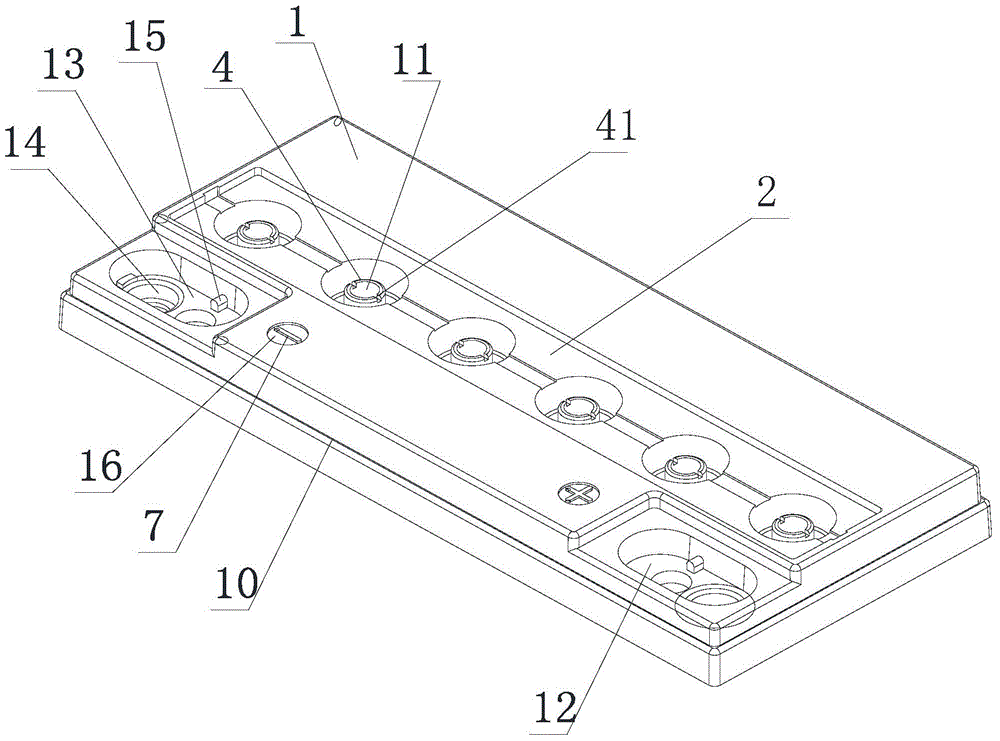
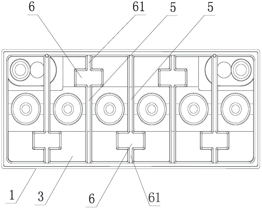
[0018] Such as figure 1 , figure 2 As shown, a battery middle cover structure includes a body 1 with a plurality of exhaust holes 11 at the top, a positive terminal groove 12 and a negative terminal groove 13 are arranged on the body 1, and the positive terminal groove 12 and the negative terminal Pole holes 14 are provided in the slots 13, at least one positioning boss 15 is provided in the positive terminal slot 12 and the negative terminal slot 13, and the bottom end of the body 1 is provided with a groove 2, and the body 1 A cavity 3 is provided at the top of the cavity 3, and several connecting columns 4 are arranged in the cavity 3. After the bottom end of the connecting column 4 passes through the cavity 3, the bottom end is flush with the bottom end of the body 1, and two adjacent At least one opening 5 is provided in the cavity 3 between the two connecting columns 4, and at least one end of each opening 5 is provided with a bridge hole 6 that is convenient for weldi...
Embodiment 2
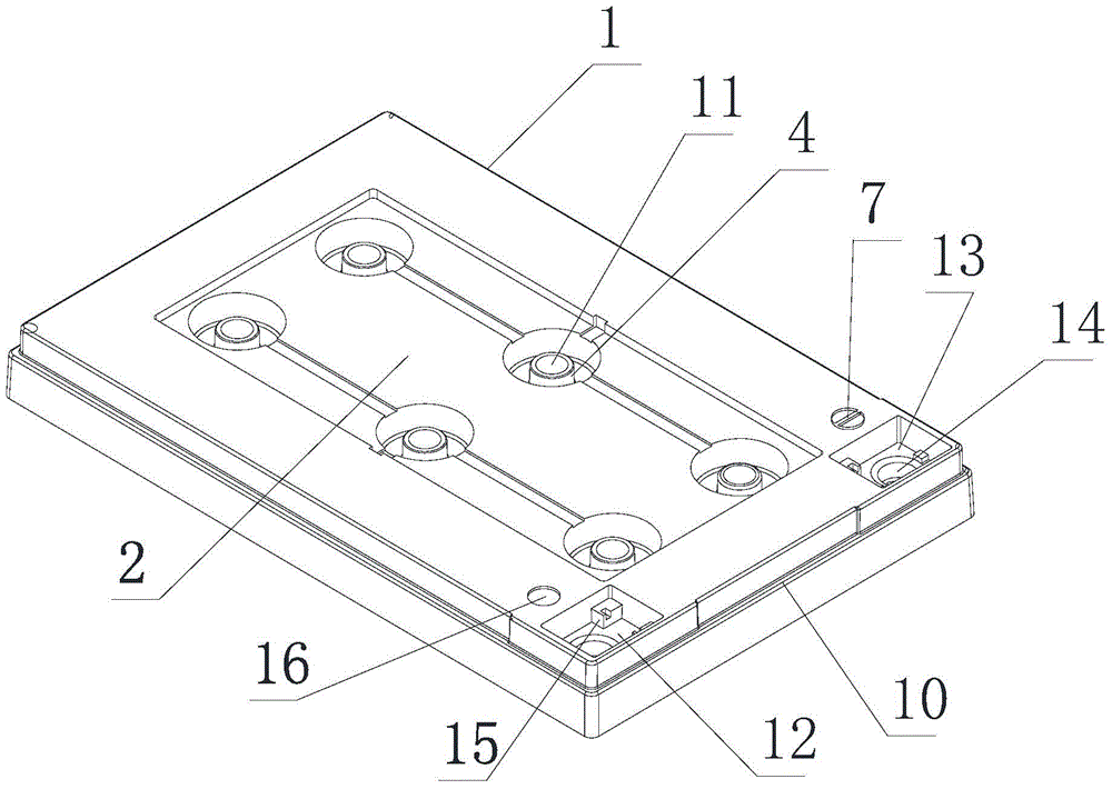
[0020] A battery middle cover structure as described in Embodiment 1, this embodiment has the following differences: image 3 , Figure 4 As shown, the six exhaust holes 11 are evenly and symmetrically distributed on the body 1 in two rows and three columns, and a bridge hole 6 is provided at both ends of each opening 5 in the vertical direction, and the opening in the horizontal direction 5 is provided with a bridge hole 6, which can adapt to a battery with a current of 12V12A. The connection is reliable, ensuring the stable performance of the battery, which is safe and reliable.
[0021] When in use, the positive and negative terminals are respectively fixedly connected in the positive terminal groove 12 and the negative terminal groove 13 through the positioning boss 15, so that the positive and negative terminals are built into the positive terminal groove 12 and the negative terminal groove 13 to ensure that the battery is placed When the positive and negative terminals ...
PUM
 Abstract
Description
Claims
Application Information