Reciprocal type microwave ferrite switch

A ferrite and microwave technology, which is applied to waveguide devices, electrical components, circuits, etc., can solve the problems that the on-off state of the switch cannot be shared, and the system cannot send and receive signals at the same time, so as to improve the switching speed and reliability and improve the performance. Effect

Inactive Publication Date: 2015-03-04
南京国睿微波器件有限公司
View PDF3 Cites 10 Cited by
  • Summary
  • Abstract
  • Description
  • Claims
  • Application Information

AI Technical Summary

Problems solved by technology

Non-reciprocity means that when the microwave signal is transmitted in the forward and reverse directions, the on-off state of the switch cannot be shared, that is, when the signal transmission direction changes, the switch state also needs to be changed; this characteristic will cause the system to be unable to send and receive signals at the same time; such as in radar There is a short-range blind zone in the application, which is not allowed to exist in many cases

Method used


Image

  • Reciprocal type microwave ferrite switch
  • Reciprocal type microwave ferrite switch

Examples


Embodiment Construction

[0013] The present invention will be further described in detail below in conjunction with the drawings.

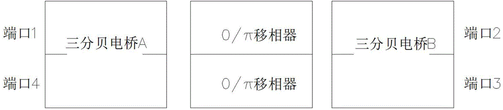
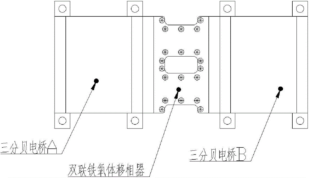
[0014] Such as figure 1 , 2 As shown, the present invention provides a reciprocal microwave ferrite switch, including a double ferrite phase shifter and three-decibel bridge A and three-decibel bridge B cascaded at both ends; three-decibel electric The two ports of bridge A are marked as port 1 and port 4; the two ports of three-decibel bridge B are marked as port 2 and port 3. The dual ferrite phase shifter contains two phase shifters. The phase shifts produced by the two phase shifters for the microwave signals passing through it are either the same (denoted as 0 state) or 180° apart (denoted as π) State), that is, the two states of 0 and π.

[0015] When the dual ferrite phase shifter is in the π state, that is, the phase shift amount of the two phase shifters differs by 180° (in actual implementation, there may be tolerance, the typical value is ±5°). If the microwave si...


PUM


Abstract

The invention provides a reciprocal type microwave ferrite switch. The reciprocal type microwave ferrite switch comprises a duplex ferrite phase shifter, a three decibels electric bridge A and a three decibels electric bridge B connected to two ends of the duplex ferrite phase shifter in a cascade connection mode; two ports of the three decibels electric bridge A is marked as the port 1 and port 4; two ports of the three decibels electric bridge b is marked as the port 2 and port 3. The duplex ferrite phase shifter comprises two phase shifters, two phase shifters have the same phase shift amount (recorded as 0 status) generated by the microwave signal or have the phase shift amount difference for 180 degrees (recorded as pi); there is no need to transform the magnetization state of the ferrite phase shifter once two ports of the four ports are switched on, and the microwave signal can be transmitted between the on ports in forward direction and reverse direction with reciprocal characteristic. The switch can be used for transmitting the receiving/sending signal without switching the on-off state while used in the microwave system; especially in the application of the radar, the close blind area will not be generated and the performance of the radar can be improved.

Description

Technical field [0001] The invention relates to a microwave ferrite switch, in particular to a reciprocal microwave ferrite switch, belonging to the field of microwave ferrite devices. Background technique [0002] Microwave ferrite devices have been widely used in electronic technology fields such as microwave communications, radar, and microwave energy. In order to realize the polarization mode of microwave signals or the rapid switching between channels, microwave ferrite switches have irreplaceable advantages. There are three types of microwave switches commonly used at present: mechanical switches, semiconductor active switches and ferrite switches. The weakness of mechanical switches is long response time, easy to wear and low reliability. The weakness of semiconductor active switches is low power capacity. The response time of the ferrite switch is between the two, but closer to the semiconductor active switch; the power capacity is also between the two, but closer to t...

Claims


Application Information

Patent Timeline
Patent Type & Authority Applications(China)
IPC IPC(8): H01P1/11
Inventor 朱兆麒罗会安韩宜冉
Owner 南京国睿微波器件有限公司
Why Eureka
Try Eureka