
Conversion compression based maximum error image compression method

An image compression, maximum error technology, applied in the field of electrical communication, can solve the problems of reduced time complexity, high time complexity, and reduced image reconstruction quality.

Active Publication Date: 2015-03-04
INST OF APPLIED MATHEMATICS HEBEI ACADEMY OF SCI
View PDF3 Cites 6 Cited by
  • Summary
  • Abstract
  • Description
  • Claims
  • Application Information

AI Technical Summary

Problems solved by technology

This method uses already processed data to predict the current pixel value, which will degrade the prediction performance, resulting in a decrease in the quality of image reconstruction.
Some scholars use the method of wavelet transform to convert the error limit of the pixel domain into the limit of the coefficient in the wavelet outline, and use the dynamic programming strategy to determine the selection of the coefficient threshold. However, the time complexity of the algorithm is relatively high, which is O (N 2 BlogB), where N represents the original data size, and B represents the size of the wavelet outline
If some scholars believe that the selection of coefficients in wavelet outlines in the past is selected from wavelet decomposition coefficients, this is not necessary and cannot guarantee the best quality wavelet outline, so they proposed a non-restricted wavelet outline technology, which The algorithmic complexity of the technique is polynomial complexity
Recently, some scholars have proposed a conversion compression method. The algorithm is also an unrestricted wavelet outline technology. The time complexity of the algorithm is further reduced to O(N), but the algorithm is not enough in the application of image compression. Effective, its compression time, image reconstruction quality and compression ratio need to be further improved

Method used


Image

  • Conversion compression based maximum error image compression method
  • Conversion compression based maximum error image compression method
  • Conversion compression based maximum error image compression method

Examples


Embodiment Construction

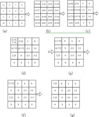
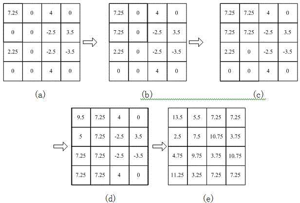
[0052] The invention relates to a maximum error image compression method based on conversion compression, the algorithm can shorten compression time, improve image compression ratio and reconstruction quality. The present invention is achieved through the following technical solutions. First, the first level of row conversion compression is performed, and the generated approximation (mean value) and detail components (conversion coefficients) are stored accordingly; then the newly generated approximation part is subjected to the first level of column conversion compression, and the corresponding approximation and details are stored at the same time component; alternately perform next-level row and column conversion and compression on the newly generated approximation until only one approximation remains; finally, the approximation and detail components can be used for data reconstruction.

[0053] The specific technical scheme is as follows:

[0054] 1. The first level of row...


PUM


Abstract

Disclosed is a conversion compression based maximum error image compression method. The method comprises performing first-stage row conversion compression and storing generated approximate values (mean value) and detail components (conversion coefficients); performing first-stage column conversion compression on the newly generated approximate value portion, and storing the corresponding approximate values and detail components; performing next-stage row and column conversion compression on the newly generated approximate values till only one next approximate value is left to obtain a final compression matrix; performing data reconstruction through the approximate value and the detail components. According to the method, the image compression method based on the maximum error criterion is used, so that errors of all points after data reconstruction are within the given range, and subsequent inquiry is facilitated; meanwhile, compared with a maximum error criterion based image compression method, the method has the advantages that compression time is shortened, and the compression ratio and the reconstruction quality of images are improved.

Description

technical field [0001] The invention relates to a conversion and compression method of image data and a data reconstruction method, belonging to the technical field of electric communication. Background technique [0002] With the development of information technology, image information is widely used in multimedia communication and computer systems. The remarkable feature of image data is the large amount of information. The huge amount of information obviously brings the problems of "not being able to store", "not being able to check quickly", and "not being able to calculate accurately" to the data processing. Although the channel transmission bandwidth is continuously widening, and the storage capacity of disks and hard disks is increasing, it still cannot solve the fundamental problem of huge data volume, and data compression technology can save data storage space and improve the efficiency of data transmission. [0003] For images, lossy compression techniques are ge...

Claims


Application Information

Patent Timeline
IPC IPC(8): H04N19/119H04N19/154
Inventor 黎彤亮李晓云黄世中
Owner INST OF APPLIED MATHEMATICS HEBEI ACADEMY OF SCI
Learn More