putter

A technology of push rod and shell, applied in the field of push rod, can solve problems such as change, and achieve the effect of simple modeling

A technology of push rod and shell, applied in the field of push rod, can solve problems such as change, and achieve the effect of simple modeling

CN104395598BActive Publication Date: 2017-08-25SCHAEFFLER TECH AG & CO KG

Image

  • putter
  • putter
  • putter

Examples


Embodiment Construction

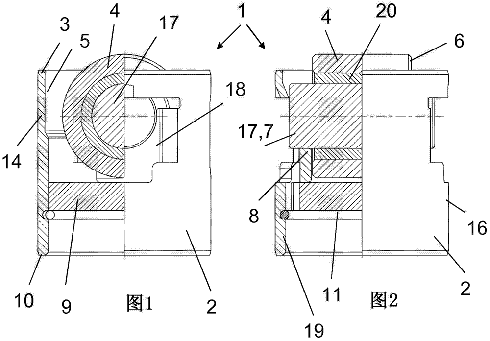
[0025] The shown pushrod 1 is used here for a high-pressure pump of diesel fuel for an internal combustion engine. The push rod 1 has a tube-like housing 2 which accommodates a roller 4 for actuating a lifting cam within an inner side 5 of the housing in the region of a first upper annular end edge 3 .

[0026] Axially below the rollers 4 , the housing 2 , here deep-drawn from sheet steel, is traversed by a separate bridge 9 . The bridge is a punched plate, the underside 11 of which faces the lower second annular end edge 10 of the housing 2 and serves as an abutment for the pump piston.

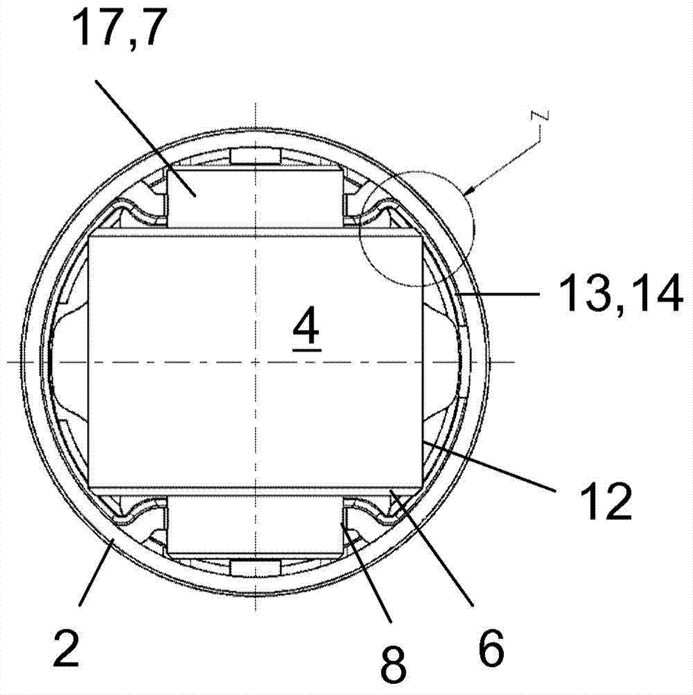
[0027] As shown, the rollers 4 run on pins 17 via rolling bearings 20 . The pins 17 are accommodated with each end (referred to here as the shaft end 7 ) in a part-cylindrical receptacle 8 of the respectively retracted region 18 of the housing 2 , which is designed as a flat part.

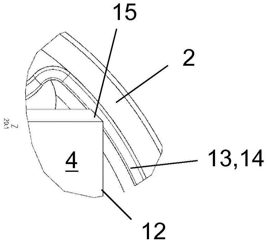
[0028] The inner side 5 of the housing 2 has a pocket-shaped material constriction. This material constrict...


PUM


Abstract

A tappet (1) for a fuel injection pump, having a tube-like housing (2), which accommodates a roller (4) for the running on a periodic lift generator inside the inner lateral surface (5) thereof in the region of a first ring end (3). This roller has axle stumps (7) projecting from the end faces (6) of the roller, by which stumps the roller sits in recesses (8) in the housing (2), wherein the housing (2) is penetrated axially by a bridge piece (9) underneath the roller (4), the underside (11) of which bridge piece, which faces a second ring end (10) of the housing (2), acts as a rest for a plunger following part. The inner lateral surface (5) of the housing (2), proceeding from the first ring end thereof in the direction of the second ring end (3, 10) and at least in the circumferential section (13) thereof, which surrounds an outer lateral surface (12) of the roller (4), has a pocket-like thinned portion of material (14), which levels out under a half of the height of the roller (4) and into which the ring edges (15) of the roller (4) project.

Description

technical field [0001] The invention relates to a push rod, in particular for a pump or a compressor, which has a tube-like casing which accommodates a useful For operating the roller of the periodic stroke generator, the roller has a one-piece or multi-piece shaft end protruding from its end side, via which the roller is located in the receptacle of the housing, wherein the housing is axially The upper side is traversed below the roller by a bridge whose underside facing the second annular end edge of the housing serves at least indirectly as an abutment for the pushrod driver. Background technique [0002] Such a push rod is known from DE 10 2010 022 318 A1. It is used in highly loaded fuel injection pumps of qualitatively or quantitatively controlled internal combustion engines. [0003] As the load-bearing capacity requirements of the plunger increase, for example due to increased speed and increased injection pressure, a more robust design of the plunger is required, ...

Claims


Application Information

Patent Timeline
25 Aug 2017
Publication
CN104395598B
IPC
F02M59/10; F04B1/04; F04B27/04; F01L1/14
CPC
F01L1/146; F01L2301/00; F01L2303/00; F01L2305/00; F02M59/102; F02M2200/03; F04B1/0408; F04B1/0426
Inventors
斯特凡·多恩; 诺伯特·盖耶