Seed throwing device for plots
A cell and rack technology, applied in the field of agricultural machinery, can solve the problems of frequent breeding, poor selection, and large labor force, and achieve the effect of improving efficiency and quality, realizing intelligence, and realizing precision.
- Summary
- Abstract
- Description
- Claims
- Application Information
AI Technical Summary
Problems solved by technology
Method used
Image

Examples
Embodiment Construction
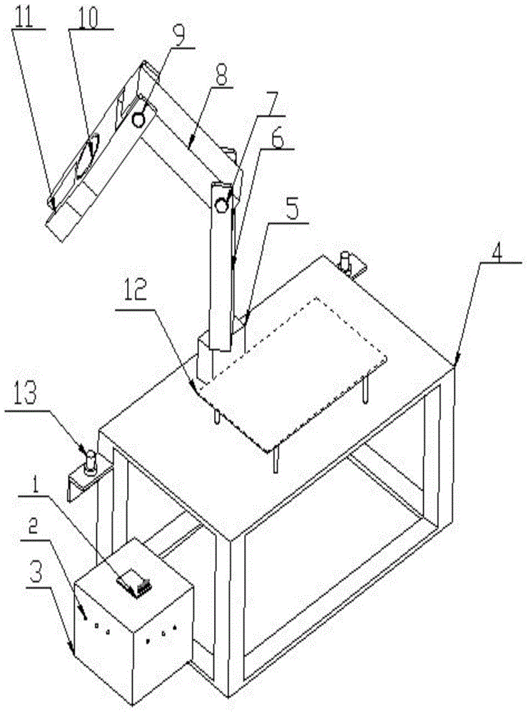
[0011] The device for throwing seeds in the community comprises a frame 4, and also includes a control platform 12 and an image acquisition system and a delivery system arranged on the frame 4; The lighting device 2 and the image acquisition device 1 are arranged inside; the delivery system includes the sowing claw 11 and the sowing claw driving mechanism; the sowing claw driving mechanism includes the mechanical arm I5, the mechanical arm II6 and the mechanical arm III8, and the mechanical arm I5 is arranged on the frame 4 , the mechanical arm II6 and the mechanical arm III8 are connected through the steering gear I7, the mechanical arm III8 is connected with the sowing claw 11 through the steering gear II9, and the sowing claw 11 is controlled by the sowing claw steering gear 10 to perform pick-and-place operations.
[0012] The control platform 12 includes a power supply system, a main controller, an auxiliary controller and a display system; the auxiliary controller is conn...
PUM
 Abstract
Description
Claims
Application Information