Rat hole blaster

A blaster, rat hole technology, applied in the direction of killing equipment, poison, hunting equipment, etc., can solve the problems of easily destroying the ecological balance, difficult to implement, and high cost, and achieves easy large-scale implementation, outstanding substantive features, and stable working performance. Effect

Active Publication Date: 2015-03-11
建泽建设股份有限公司
View PDF8 Cites 4 Cited by
  • Summary
  • Abstract
  • Description
  • Claims
  • Application Information

AI Technical Summary

Problems solved by technology

[0003] At present, there are four types of rodent control methods: physical rodent control, chemical rodent control, biological rodent control, and ecological rodent control. For flooding, detaining, clicking, ultrasonic, sticky rodents, etc., the physical rodent control method is the safest and does not damage the ecological environment, but the disadvantages of this method are labor-intensive, high cost, large investment, and not suitable for large-scale implementation; Rodent control can be divided into poisonous bait method and poisonous gas method. This method is easy to cause human and animal poisoning, and in the long run, it will eventually endanger the ecological environment. Biological rodent control is mainly to protect and use natural enemies to control rodent damage. Huge and difficult to implement; ecological control is mainly to destroy and change the suitable living conditions and environment of rodents, making it unfavorable for the habitat and reproduction of rodents, and increasing their mortality. This method has a slow effect and belongs to long-term control; therefore As far as the market is concerned, there is no efficient, low-cost, safe, reliable, non-toxic, non-destructive to the ecological environment, and relatively easy large-scale implementation of rodent control equipment.

Method used


Image

  • Rat hole blaster
  • Rat hole blaster

Examples


Embodiment Construction

[0017] The specific implementation manners of the present invention will be further described in detail below in conjunction with the accompanying drawings and embodiments. The following examples are used to illustrate the present invention, but are not intended to limit the scope of the present invention.

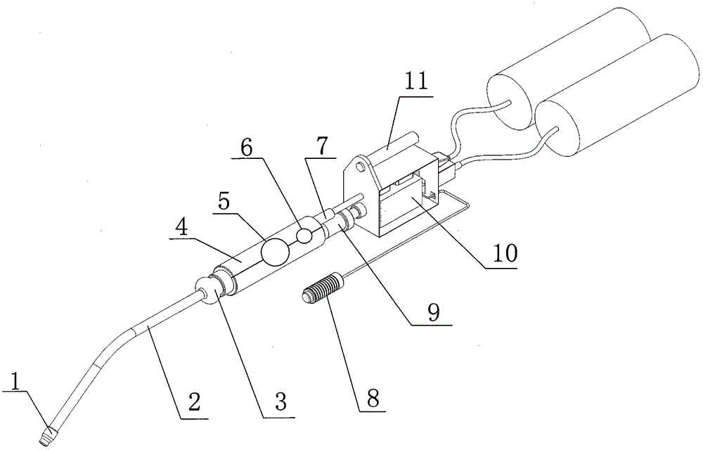
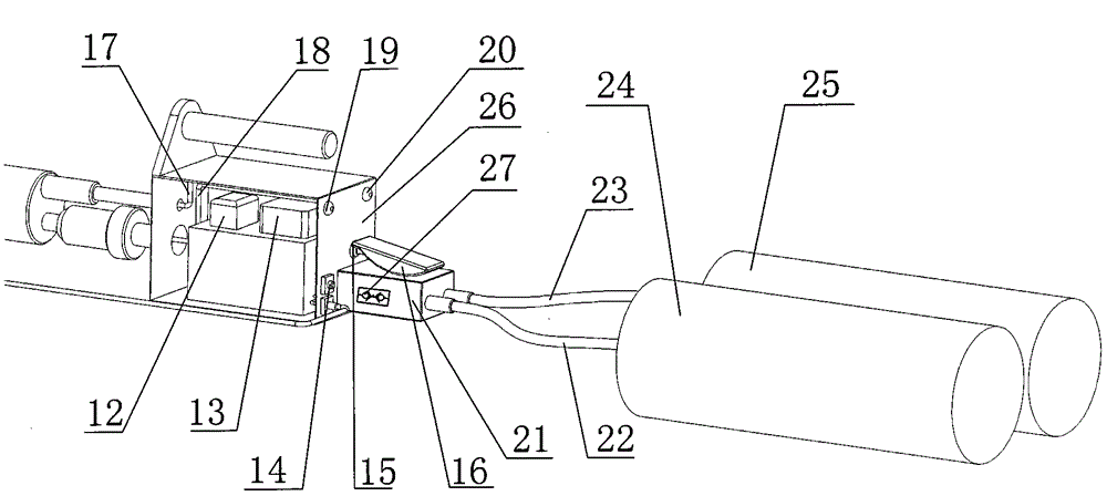
[0018] see figure 1 and figure 2 Shown mouse hole blaster comprises fuel tank, gas jet pipeline 4 and blasting controller 26, and blasting controller 26 is arranged on the pipeline that fuel tank communicates with gas jet pipeline 4; Fuel tank is made up of propane high-pressure gas tank 24 and oxygen high-pressure gas tank 25 components; the front end of the jet pipeline 4 is provided with an extension tube 2, and the extension tube 2 is provided with an ignition head 1; the rear end of the jet pipeline 4 is respectively connected to the sleeve 7 of the oxygen branch circuit and the reset check valve of the propane branch circuit 9 are connected, and are connected with...


PUM


Abstract

The invention relates to a rat hole blaster which comprises a fuel tank, a gas injection pipeline and a blasting controller, wherein the blasting controller is arranged on a pipeline for communicating the fuel tank with the gas injection pipeline; the fuel tank is composed of a propane high-pressure gas tank and an oxygen high-pressure gas tank; an extension tube is arranged at the front end of the gas injection pipeline, and an ignition head is arranged on the extension tube; the rear end of the gas injection pipeline is respectively connected with a sleeve of an oxygen branch and a reset type non-return valve of a propane branch, and is connected with the fuel tank by virtue of an oxygen gas conveying pipeline and a propane gas conveying pipeline inside the blasting controller; a spark plug and the non-return valve are arranged inside the gas injection pipeline; mixture gas after being mixed in the fuel tank is injected into a rat hole channel by virtue of the gas injection pipeline and the extension tube; under the control of the blasting controller, the ignition head is used for igniting to ignite the mixture gas inside the rat hole, so that the blasting is completed. The rat hole blaster disclosed by the invention is non-hazardous, does not destroy the ecological environment, and is compact in structure, safe and reliable, and wide in scope of application.

Description

technical field [0001] The invention belongs to the technical field of rodent damage control, and in particular relates to a rat hole blaster. Background technique [0002] Rats spread diseases, steal grain and food, destroy forests, grasslands, farmland, and gnaw objects, buildings, communication facilities, furniture and clothing, etc., which have brought huge losses to human life and property. Because rodent infestation is very harmful to agricultural and animal husbandry production and people's life, so the prevention and control of rodent infestation has far-reaching significance to promote agricultural and animal husbandry production, develop national economy, and protect people's health. [0003] At present, there are four types of rodent control methods: physical rodent control, chemical rodent control, biological rodent control, and ecological rodent control. For flooding, detaining, clicking, ultrasonic, sticky rodents, etc., the physical rodent control method is ...

Claims


Application Information

Patent Timeline
Patent Type & Authority Applications(China)
IPC IPC(8): A01M27/00
Inventor 程锦远
Owner 建泽建设股份有限公司
Why Eureka
Try Eureka