Automatic wake-up circuit applicable to cardiac pacemaker

A cardiac pacemaker and automatic wake-up technology, applied in electrotherapy, treatment, etc., can solve problems such as complicated operation, and achieve the effects of simple operation, cost reduction, and simple circuit structure

Active Publication Date: 2015-03-11
XI AN JIAOTONG UNIV
View PDF3 Cites 2 Cited by
  • Summary
  • Abstract
  • Description
  • Claims
  • Application Information

AI Technical Summary

Problems solved by technology

This method requires manual intervention and is complex to operate

Method used


Image

  • Automatic wake-up circuit applicable to cardiac pacemaker
  • Automatic wake-up circuit applicable to cardiac pacemaker
  • Automatic wake-up circuit applicable to cardiac pacemaker

Examples


Embodiment Construction

[0016] The present invention will be described in further detail below in conjunction with the accompanying drawings.

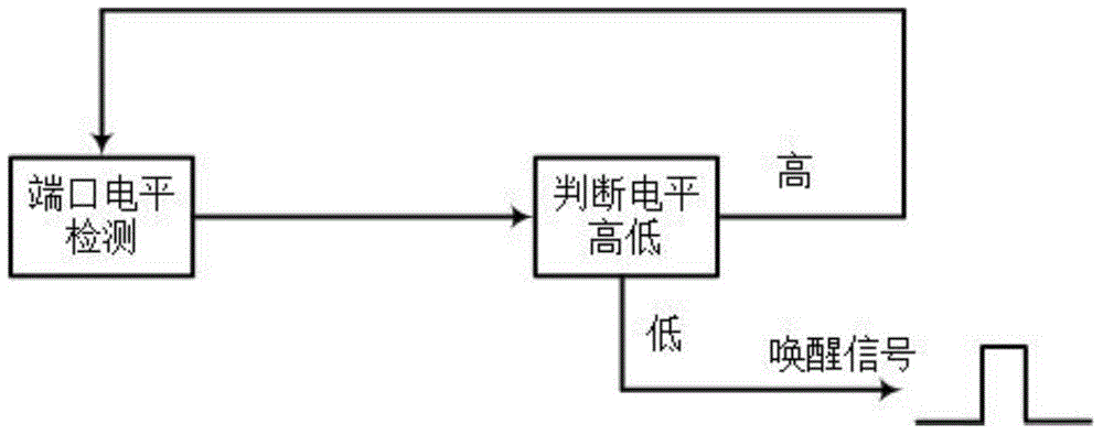
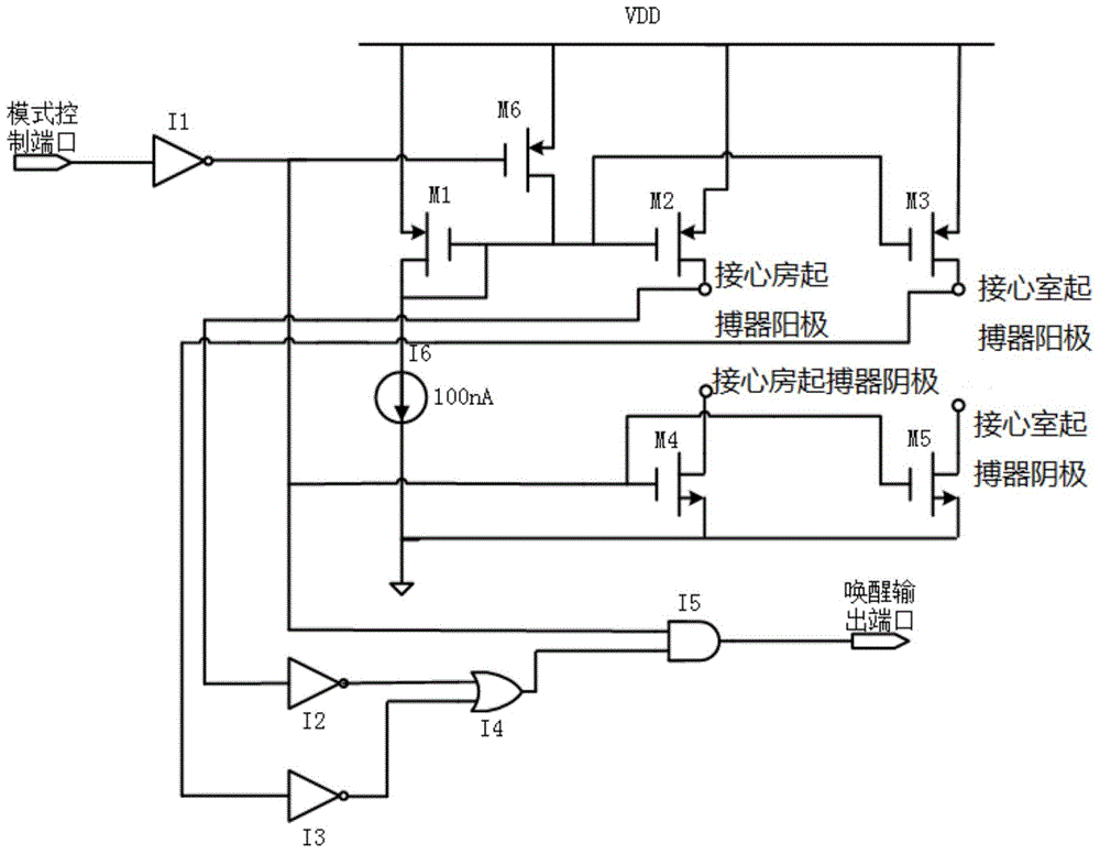
[0017] see figure 1 and 2 , the present invention includes a port level detection circuit and a high-low level judgment circuit; the output end of the port level detection circuit is connected to the input end of the high-low level judgment circuit, and the high-level output end of the high-low level judgment circuit is connected to the port level Detection circuit, the low level output is connected to the cardiac pacemaker. The port level detection circuit includes: a first MOS transistor M1, the source terminal of the first MOS transistor M1 is connected to the power supply voltage, the gate terminal and the drain terminal are connected to the current source I6; the gate terminal of the first MOS transistor M1 is also connected to the second The gate terminal of the MOS transistor M2, the gate terminal of the third MOS transistor M3 and the drain of the s...


PUM


Abstract

The invention relates to an automatic wake-up circuit applicable to a cardiac pacemaker. A port level detection circuit and a high and low level judgment circuit are provided. The output end of the port level detection circuit is connected with the input end of the high and low level judgment circuit; the high level output end of the high and low level judgment circuit is connected to the port level detection circuit; the low level output end of the high and low level judgment circuit is connected to the cardiac pacemaker. Therefore, whether or not the cardiac pacemaker is connected to the heart can be judged through the port level detection circuit, the cardiac pacemaker is automatically controlled to switch to a running mode, no manual intervention is required, and operating is simple; meanwhile, the circuit is simple in structure and low in power consumption, a wake-up signal is sent out to activate the cardiac pacemaker only when the fact that the cardiac pacemaker is implanted in the human body is detected, management efficiency of pacemaker power consumption is effectively improved, battery power of the cardiac pacemaker is saved, and cost is lowered.

Description

technical field [0001] The invention belongs to the field of integrated circuits, and in particular relates to an automatic wake-up circuit applied to cardiac pacemakers. Background technique [0002] A cardiac pacemaker is powered by a single non-replaceable battery, which is generally required to work for 10 years or more, and the power consumption requirements are extremely demanding. For a pacemaker, it takes a long time to wait from the completion of production to implantation into the human body. During this period, the pacemaker should be in a dormant state to ensure that most of its internal modules do not work, so that the entire chip consumes power Minimal, reducing pacemaker battery energy waste. At present, the main method for changing the working state of the pacemaker is: after the pacemaker is implanted into the human body, the pacemaker is programmed to enter the normal working mode through an external program controller. This method requires manual interve...

Claims


Application Information

Patent Timeline
Patent Type & Authority Applications(China)
IPC IPC(8): A61N1/37
Inventor 张瑞智赵阳张鸿许江涛李嘉张杰
Owner XI AN JIAOTONG UNIV
Why Eureka
Try Eureka