Oil filter

An oil filter device and filter plate technology, applied in the field of filters, can solve the problems of small oil filter flow, reduced economic benefits, low efficiency, etc., and achieve the effects of convenient cleaning, reasonable design and simple structure

Inactive Publication Date: 2015-03-11
常州市兰迪电器有限公司
View PDF0 Cites 0 Cited by
  • Summary
  • Abstract
  • Description
  • Claims
  • Application Information

AI Technical Summary

Problems solved by technology

The current oil filtering device includes a cylinder with a paper core installed inside the cylinder, through which the oil is filtered. This structure has a small oil filtrat...

Method used


Image

  • Oil filter

Examples


Embodiment Construction

[0010] The present invention will be further described below in conjunction with the accompanying drawings and specific embodiments.

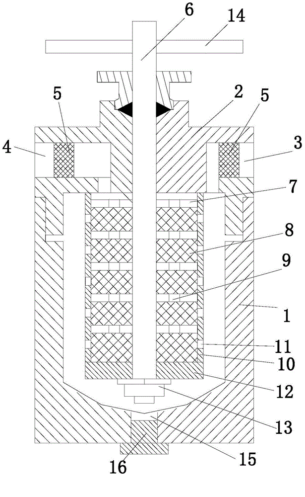
[0011] see figure 1 , an oil filtering device, comprising a cylinder body 1 with a circular lower end as an open end and an upper end as a closed end, and a cover body 2 connected to the cylinder body for sealing the open end of the cylinder body, and the cylinder body and the cover body are connected by threads , the cover body is respectively provided with an oil inlet hole 3 and an oil outlet hole 4 communicating with the inside of the cylinder. There is a filtering structure in the body, and also includes a positioning shaft 6 for assembling the filtering structure. One end of the positioning shaft passes through the cover and is outside the cylinder, and the other end is in the cylinder. The above-mentioned filtering structure is assembled on the positioning shaft in the cylinder. The structure includes a plurality of filter plates 7 slee...


PUM


Abstract

The invention relates to the technical field of filters, in particular to an oil filter. The oil filter comprises a cylinder body with a circular lower end which is an open end and an upper end which is a sealed, and a cover body connected to the cylinder body and used for sealing the open end of the cylinder body, wherein an oil charging hole and an oil discharging hole both communicated with the inside of the cylinder body are respectively formed in the cover body; the cylinder body is internally provided with a filter structure; the oil filter also comprises a positioning shaft used for assembling the filter structure; one end of the positioning shaft penetrates through the cover body and is arranged outside the cylinder body; the other end of the positioning shaft is arranged inside the cylinder body; the filter structure is assembled on the positioning shaft in the cylinder body; the filter structure comprises a plurality of filter plates which are arranged on the positioning shaft in a sleeving manner; a filter element is arranged between the adjacent filter plates; oil through holes are formed in the filter plates; the oil passing holes of the filter plates form an oil channel which is communicated with the oil discharging hole. The oil filter is simple in structure, reasonable in design and convenient to wash, and can be used for efficiently filtering oil liquid in a high-flow manner.

Description

technical field [0001] The invention relates to the technical field of filters, in particular to an oil filter device. Background technique [0002] In the production of enterprises, mechanical equipment needs to filter and recycle the oil used to ensure that the oil is clean and various parameters meet the requirements for safe operation of the equipment, and to save oil. The current oil filtering device includes a cylinder with a paper core installed inside the cylinder, through which the oil is filtered. This structure has a small oil filtration flow rate, low efficiency, and long time for impurity filtration, which affects the start-up time and overhaul progress of the equipment. , but also reduce the economic efficiency. Contents of the invention [0003] In view of the above problems, the object of the present invention is to provide an oil filtering device with reasonable structural design, large oil filtering capacity, high efficiency and short impurity filtering ...

Claims


Application Information

Patent Timeline
IPC IPC(8): B01D36/02
Inventor 张剑
Owner 常州市兰迪电器有限公司
Why Eureka
Try Eureka