Intelligent magneto-rheological deceleration strip

A deceleration belt and magneto-rheological technology, applied in the field of intelligent magnetorheological deceleration belts, can solve the problems that vibration and bumps cannot be completely eliminated, there are flexible impacts, vehicle bumps, etc., and achieve simple structure, prolong service life, and increase riding The effect of comfort

Inactive Publication Date: 2015-03-11
SICHUAN UNIV
View PDF7 Cites 20 Cited by
  • Summary
  • Abstract
  • Description
  • Claims
  • Application Information

AI Technical Summary

Problems solved by technology

Existing deceleration belts have the same deceleration effect on vehicles passing by at different speeds, especially when the vehicle speed is lower than the specified speed, the vehicle will also bump, which will not only cause discomfort to passengers, but also cause discomfort to the vehicle. itself can also negatively affect
Chinese patent CN101818485B discloses a deceleration belt without rigid impact on the vehicle. This structure can overcome the rigid impact between the deceleration belt and the vehicle, but there is still a flexible impact, which cannot completely eliminate the vibration and bumpy feeling of the vehicle at low speeds.
Chinese patent CN103061287A discloses a magneto-rheological deceleration belt, which can detect the speed of the vehicle in advance and then change the stiffness of the deceleration belt, reducing the vibration of low-speed vehicles, but needs to provide a speed sensor and external power supply equipment, the system is complex and economical

Method used


Image

  • Intelligent magneto-rheological deceleration strip
  • Intelligent magneto-rheological deceleration strip
  • Intelligent magneto-rheological deceleration strip

Examples


Embodiment Construction

[0033] The present invention will be further described below in conjunction with the accompanying drawings and embodiments, but the present invention is not limited to the following embodiments.

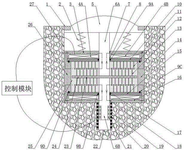
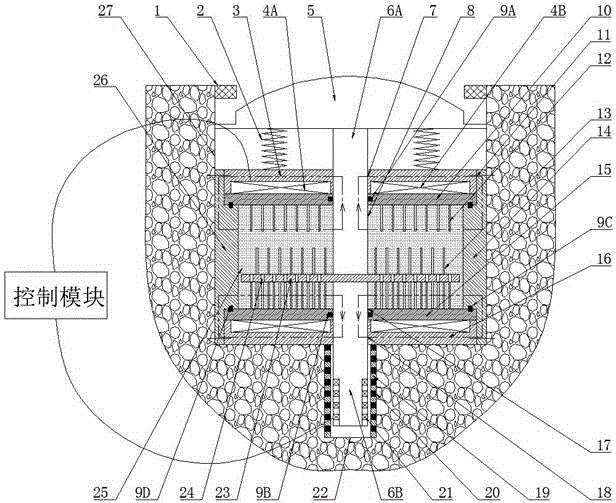
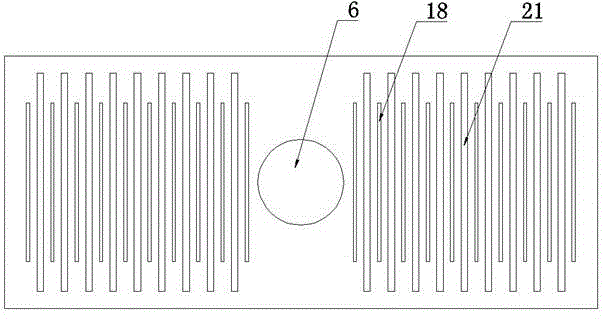
[0034]Intelligent magneto-rheological deceleration belt mainly includes deceleration belt (5), spring (2), connecting shaft I (6A), connecting shaft II (6B), working plate (23), driven friction plate group (12), active friction Sheet group (13), excitation coil I (4A), excitation coil II (4B), ring magnet (20), ring yoke (19), coil winding (21), magnetorheological fluid (25) and control module, In the lane speed limit area, at least one square long slot (27) is provided perpendicular to the length direction of the lane, and a rectangular cylinder is placed in the square long slot (27);

[0035] Rectangular cylinder includes lower bottom plate (16), upper cover plate (3), left side baffle plate (26) and right side baffle plate (14), lower bottom plate (16) and left side baffle pla...


PUM


Abstract

The invention discloses an intelligent magneto-rheological deceleration strip. The intelligent magneto-rheological deceleration strip comprises a deceleration strip, a spring, a connecting shaft I, a connecting shaft II, a working panel, a driven friction plate unit, a drive friction plate unit, an annular magnet, an annular magnet yoke, a wire winding, a magneto-rheological fluid, and a control module; a square elongated slot is opened in a lane speed limit area perpendicular to the length direction of the lane; a rectangular tank filled with the magneto-rheological fluid is placed inside the square elongated slot; the working panel which is provided with strip-type through holes and the drive friction plate unit on the surface thereof is placed inside the rectangular tank; the upper and lower surfaces of the working panel are further respectively fixed with the connecting shaft I and the connecting shaft II; the other end of the connecting shaft I is connected with the deceleration strip; the other end of the connecting shaft II is wrapped with the wire winding and inserted into the annular magnet and the annular magnet yoke inside a circular blind hole at the bottom of the square elongated slot. The intelligent magneto-rheological deceleration strip can automatically adjust the rigidity of the deceleration strip based on the car speed, thereby decelerating a high-speed car, whereas letting a low-speed car pass through comfortably. The intelligent magneto-rheological deceleration strip is simple in structure and good in economical efficiency.

Description

technical field [0001] The invention relates to a deceleration belt used on roads, in particular to an intelligent magneto-rheological deceleration belt whose stiffness can be automatically adjusted according to the vehicle speed and which is self-powered. Background technique [0002] With the development of our country's economy and the advancement of science and technology, the road transportation industry has also developed rapidly, but the traffic accident rate has also increased. Among them, speeding is the number one killer of road traffic accidents. Traffic safety has become a serious social problem. In order to prevent the occurrence of traffic accidents as far as possible, the traffic department or enterprises and institutions have set special measures at road crossings, industrial and mining enterprises, school crossings, residential area entrances, parking lots and expressway toll stations, etc. A row or several rows of speed bumps are set up on the road section...

Claims


Application Information

Patent Timeline
Patent Type & Authority Applications(China)
IPC IPC(8): E01F9/047H02K44/08E01F9/529
CPCH02K44/08
Inventor 吴杰蒋学争姚进李华李青涛曹修全
Owner SICHUAN UNIV
Why Eureka
Try Eureka