Overflow dam with dam face cantilever sills for current diversion and energy dissipation

An overflow dam and energy dissipation technology, which is applied in the direction of dams, gravity dams, water conservancy projects, etc., can solve the problems of increased impact on the front end of the stilling pool, poor energy dissipation effect, and damage to the bottom plate of the stilling pool. The effect of energy dissipating effect

Active Publication Date: 2015-03-11
SICHUAN UNIV
View PDF7 Cites 31 Cited by
  • Summary
  • Abstract
  • Description
  • Claims
  • Application Information

AI Technical Summary

Problems solved by technology

[0005] However, as the height of the dam increases, the water flow stretched by the wide-tail pier will concentrate during the movement in the air. The effect is that the velocity of the water flow in the upper layer is small and the velocity of the water flow in the lower layer is large. Therefore, when the air movement distance is large, the trajectories of the water flow emitted from different posi...

Method used


Image

  • Overflow dam with dam face cantilever sills for current diversion and energy dissipation
  • Overflow dam with dam face cantilever sills for current diversion and energy dissipation
  • Overflow dam with dam face cantilever sills for current diversion and energy dissipation

Examples


Embodiment 1

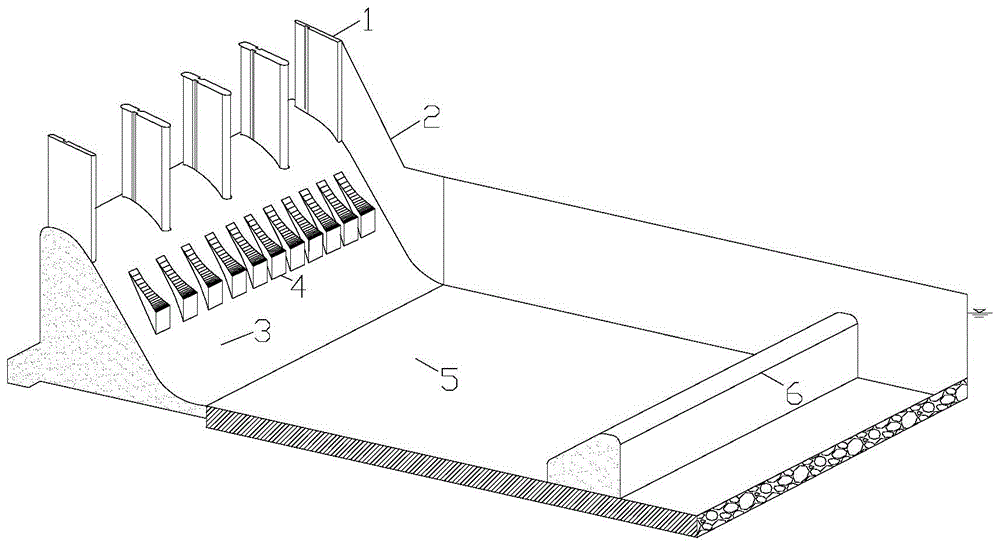
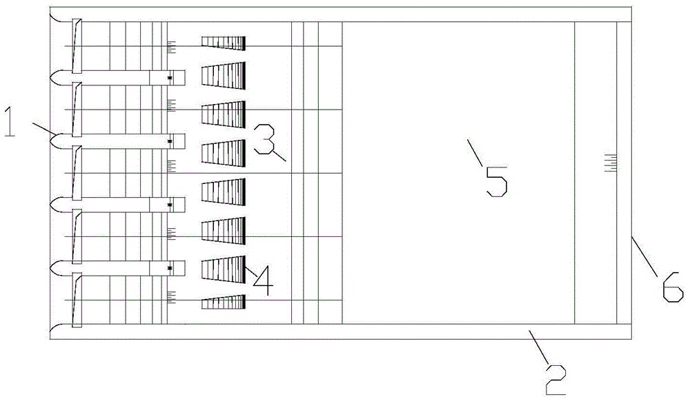
[0026] The overflow dam of the dam surface of the present embodiment is raised to divert and dissipate energy, and its structure is as attached figure 1 And attached figure 2 As shown, the discharge slope surface 3 of the overflow dam is connected straightly with the bottom of the stilling tank 5, and the side wall 2 of the discharge slope surface is connected to the protective side wall of the stilling tank behind. The crest of the overflow dam is designed with several The water body flow area is divided into several gate piers 1 with surface holes, and the discharge slope of the overflow dam is provided with a number of anti-arc shunt ridges 4 distributed at intervals, so that part of the water flow from the surface holes passes through the anti-arc ridges to lift The form of water flow enters the second half area of ​​the stilling pool, while another part of the water flows into the front half area of ​​the stilling pool through the flow channel between the two ridges. Am...

Embodiment 2

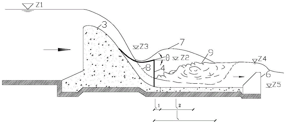
[0028] In the overflow dam of the present embodiment, the dam face lifts the ridge to divert flow and dissipate energy. The discharge slope surface 3 of the overflow dam is connected to the bottom of the stilling basin 5 through a drop ridge, and the side wall 2 of the discharge slope surface is connected to the stilling basin behind. The protective side wall and the crest of the overflow dam are designed with a number of gate piers 1 that divide the water body flow area into a number of surface holes, and the discharge slope of the overflow dam is provided with a number of anti-arc diversion risers 4 that are distributed at intervals, so that from Part of the water flow from the surface hole enters the second half of the stilling pool in the form of deflected flow through the anti-arc ridge, while the other part of the water flows into the front half of the stilling pool through the flow channel between the two ridges. Among them, the distance between the central axes of two a...


PUM


Abstract

The invention discloses an overflow dam with dam face cantilever sills for current diversion and energy dissipation. The tank bottom of an energy dissipation tank is connected to the rear part of an overflow slop of the overflow dam. A protection side wall of the energy dissipation tank is connected to the rear part of a side wall of the overflow slope. A plurality of gate piers used for dividing a fluid flow-by area into a plurality spillway are arranged on the dam top of the overflow dam. The overflow slope of the overflow dam is provided with a plurality of current diversion cantilever sills distributed in a spaced manner, so that one part of water current coming from the spillways flows through the upper sill surfaces of the cantilever sills and enters the rear area of the energy dissipation tank in a form of cantilever current while the other part of water current flows into the front area of the energy dissipation tank through flow channels between each two cantilever sills and achieves energy dissipation through dispersion of the water current entering the energy dissipation tank. The energy dissipation mode provided by the invention is totally different from those in the prior art and is distinct in energy dissipation effect.

Description

technical field [0001] The invention belongs to the field of flood discharge and energy dissipation of hydraulic structures in water conservancy and hydropower projects, and in particular relates to an overflow dam whose dam surface is designed with a ridge diversion energy dissipation structure. Background technique [0002] In water conservancy and hydropower projects, the gravity dam is a commonly used dam type. Generally speaking, the construction material of the gravity dam is concrete, so the dam body is often used for flood discharge. For an overflow dam that discharges flood through the dam body, a stilling basin is generally built behind the dam, and a hydraulic jump is used to dissipate energy. However, the energy dissipation rate of the hydraulic jump is generally low, ideally about 60-70%, sometimes even smaller. [0003] With the increase of the height of the dam, the velocity of the discharged water also increases rapidly, and its energy also increases rapidly...

Claims


Application Information

Patent Timeline
IPC IPC(8): E02B8/06E02B7/10
CPCE02B8/06
Inventor 邓军许唯临田忠张法星刘善均张建民王韦曲景学刘文周茂林
Owner SICHUAN UNIV
Why Eureka
Try Eureka