
A high temperature and high pressure cementing cement sheath mechanical integrity testing device and method

A high temperature and high pressure, cementing technology, applied in construction and other directions, can solve the problems of rarely considering the stress impact of cement sheath, and not realizing the quantitative evaluation of cement sheath mechanics.

Active Publication Date: 2017-07-11
SOUTHWEST PETROLEUM UNIV
View PDF8 Cites 0 Cited by
  • Summary
  • Abstract
  • Description
  • Claims
  • Application Information

AI Technical Summary

Problems solved by technology

[0006] These research methods and means are all trying to simulate the real stress state of the cement sheath under the downhole working conditions, but there are also a lot of disadvantages
The software simulation data is calculated on the basis of a large number of simplifications, and the reliability of the data must be verified by equivalent physical experiments. The various cement sheath integrity simulators are actually only the measurement of "stone" and have not been realized. "Ring" structure, but the stress states brought by the two different structures are very different. More importantly, based on the limitations of experimental equipment and conditions, little consideration is given to the influence of cement sheath on high temperature, high pressure and the changes of the two. The stress impact of the cement sheath has not yet achieved a quantitative assessment of the mechanical integrity of the cement sheath

Method used


Image

  • A high temperature and high pressure cementing cement sheath mechanical integrity testing device and method

Examples


Embodiment Construction

[0037] The present invention will be further described below in conjunction with accompanying drawing.

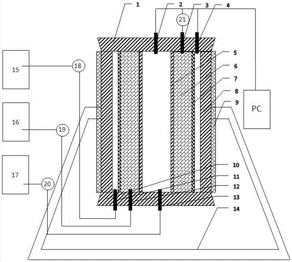
[0038] see figure 1 .

[0039] A high-temperature and high-pressure well cementing cement sheath mechanical integrity testing device includes a cement sheath curing mold and a testing work platform.

[0040] The cement sheath maintenance mold is composed of left and right molds and internal pressure sleeves. The left and right molds form a hollow cylinder with a circular interior and a square exterior. The internal pressure sleeve is located in the hollow cylinder, and the internal pressure The annular space formed by the sleeve pipe and the hollow cylinder is filled with cement slurry, and its upper and lower ends are sealed.

[0041] The test working platform includes a test body and a support. The test body is located on the support 14. There are upper plugs 1 and lower plugs 10 at the upper and lower ends respectively. The test body is mainly composed of an internal pre...


PUM


Abstract

The invention discloses a device and a method for testing the mechanical integrity of a high-temperature high-pressure well cementation cement sheath. The device comprises a cement sheath maintenance mould and a test working platform. The method comprises the following steps of (1) arranging an internal pressure casing into a hollow column formed by connecting left and right moulds, filling cement paste, and sealing upper and lower ends of the hollow column; (2) maintaining the cement sheath maintenance mould, taking the cement sheath and the internal pressure casing out, and putting the cement sheath and the internal pressure casing on the test working platform; (3) injecting water into an annular space of an annular pressure sleeve and a pressure bearing cylinder through an annular pressure inlet, injecting water into the casing through an internal pressure inlet, controlling the temperature at the target temperature, adjusting the annular pressure and the internal pressure to target pressure, recording the change of reading of a rotor flow meter, and showing that the mechanical integrity of the cement sheath is damaged at a time point that flow is obviously increased; (4) taking the cement sheath out, observing and detecting. The device and the method are suitable for simulating the damage and degradation of the cement sheath under different string structures in the later production process of an oil-gas well.

Description

technical field [0001] The invention relates to a cement sheath mechanical integrity testing device and method in the field of oil and gas well engineering cementing, in particular to a device and method for testing the mechanical integrity of the cement sheath under high temperature and high pressure conditions, which can simulate the double impact of the complex mechanical load and thermal stress on the formation and casing of the cement sheath, and can perform dynamic testing. Devices and methods for its mechanical integrity. [0002] technical background [0003] Oil and gas well cementing means that after the drilling operation reaches a certain depth, the casing is inserted into the wellbore, and the cement slurry is injected into the outer annular space of the casing to a predetermined position, so that it can be rapidly condensed and hardened within a predetermined time to form a high-quality, complete, The process of cement sheath with good interlayer isolation abili...

Claims


Application Information

Patent Timeline
Patent Type & Authority Patents(China)
IPC IPC(8): E21B47/005
CPCE21B47/005
Inventor 刘健郭小阳常培敏李早元程小伟李明张凯谢和
Owner SOUTHWEST PETROLEUM UNIV
Learn More