Construction structure and construction method for strengthening stratum at end of shield tunnel

A technology of shield tunnel and construction method, which is applied to tunnels, tunnel lining, earthwork drilling, etc., can solve the problems of inability to carry out mixing piles and rotary jetting piles, construction, and the reinforcement structure is not strong, so as to prevent water leakage and sand leakage. Effect

Inactive Publication Date: 2015-03-11
HAINAN UNIVERSITY
View PDF5 Cites 27 Cited by
  • Summary
  • Abstract
  • Description
  • Claims
  • Application Information

AI Technical Summary

Problems solved by technology

[0004] However, there are still deficiencies and defects in the existing technology. The existing reinforcement methods and reinforcement methods will not be able to carry out the construction of mixing piles and jet grouting piles due to the limitations of the ground environment, and due to the low strength of t...

Method used


Image

  • Construction structure and construction method for strengthening stratum at end of shield tunnel
  • Construction structure and construction method for strengthening stratum at end of shield tunnel
  • Construction structure and construction method for strengthening stratum at end of shield tunnel

Examples


Embodiment 1

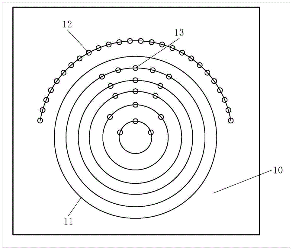
[0044] figure 1 It is a schematic plan view of the construction structure of Embodiment 1 to strengthen the strata at the end of the shield tunnel, as figure 1 As shown, a construction structure for strengthening the strata at the end of a shield tunnel provided in this embodiment includes:

[0045] A working well surface 10, the working well surface 10 includes a working well opening 11 to be operated by the shield machine, which is equal in radius to the shield machine;

[0046] A plurality of advanced grouting long pipe sheds 12 are arranged perpendicular to the working well surface 10 to be shielded to be operated on the top of the door 11 of the working well to be shielded. The vertical distances between the centers of the working well portals 11 are equal, and the ring spacing between the adjacent long pipe sheds 12 for the advanced grouting is equal;

[0047] A plurality of horizontal grouting pipes 13 are arranged vertically to the working well surface 10 to be shiel...

Embodiment 2

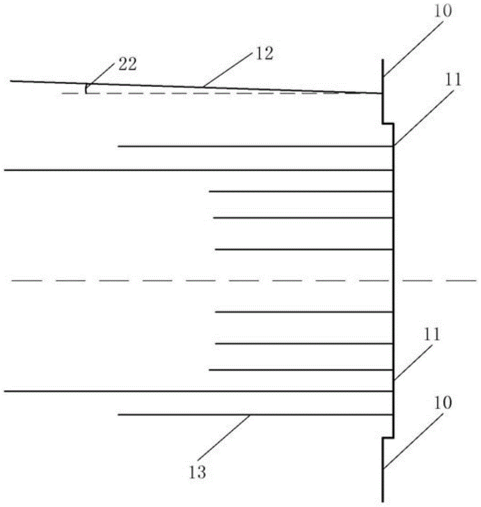
[0054] figure 2 It is the cross-sectional view of the construction structure of embodiment two reinforcement shield tunnel head formations, as figure 2 As mentioned above, on the basis of the first embodiment, the plurality of advanced grouting long tube sheds 12 are arranged above the door 11 of the working well to be shielded to be operated at an angle 22 of a certain size upward with the horizontal line. For example, the included angle 22 may be set to 1°.

[0055] The above-mentioned technical scheme, by setting a certain angle between multiple long pipe sheds with advanced grouting and the horizontal line, avoids the front end drooping into the tunnel operation area due to the gravity of the pipe shed itself when installing the pipe shed, which affects the construction quality and operation safety .

Embodiment 3

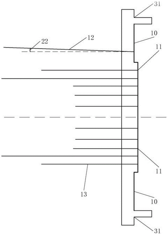
[0057] image 3 It is the sectional view of the construction structure of embodiment three reinforcement shield tunnel end formations, as image 3 As shown, each of the advanced grouting long pipe sheds has the same length, and the length can be set to 12m. Each of the said advanced grouting long pipe sheds is composed of a variety of steel pipes with different specifications, and grouting holes are drilled on the steel pipes. The length of the steel pipe sections of different specifications can be 1.0m, 1.5m, 2.0m or 3.0m respectively.

[0058] On the basis of the above-mentioned embodiments, specifically, the working well surface is also fixed with a working well enclosure structure 31, and then the steel pipes in each of the advanced grouting long pipe sheds 12 are placed on the working well enclosure structure 31. No grouting holes are drilled within a certain distance on one side, and the certain distance may be within 1m.

[0059] The above technical scheme, by setting...


PUM


Abstract

The invention provides a construction structure and a construction method for strengthening the stratum at an end of a shield tunnel. The construction structure comprises a working well face which comprises a to-be-shielded working well portal having the same radius with a shield machine, a plurality of pre-grouting long pipe-sheds arranged above the to-be-shielded working well portal perpendicularly to the to-be-shielded working well portal, and a plurality of horizontal grouting pipes arranged in the to-be-shielded working well portal perpendicularly to the to-be-shielded working well portal; a PVC sleeve valve pipe with a grouting hole is arranged in each horizontal grouting pipe. The plurality of pre-grouting long pipe-sheds and the plurality of horizontal grouting pipes are arranged above and inside the working well portal to form a cup shape together to strength and protect the soil above and inside the working area of the stratum at the end of the shield tunnel, and therefore, the case that the construction quality is affected by water leakage and sand leakage due to insecure soil above and inside the working area in the working process is prevented, and therefore, the shield is capable of going in and out the portal safely.

Description

technical field [0001] The invention relates to a shield tunneling construction method, in particular to a construction structure and construction method for reinforcing the ground at the end of a shield tunnel. Background technique [0002] The end reinforcement of shield tunnel is a key link in the construction of shield tunneling method, which has great construction risks. When the shield enters and exits the tunnel, the underground continuous wall in the tunnel area must be broken first, and all steel bars must be cut off. The time required for demolition of the cave door is very tight and the construction is difficult. After the portal is demolished, the strength and sealing of the reinforced body are very high. If the reinforcement effect is not good, the gap between the shield and the portal and the surface settlement will easily occur during the demolition of the portal, which will endanger the nearby underground pipelines and building security. In order to preven...

Claims


Application Information

Patent Timeline
IPC IPC(8): E21D11/00E21D11/10
CPCE21D11/105
Inventor 胡俊李艳荣曾晖赵联桢佳琳
Owner HAINAN UNIVERSITY
Why Eureka
Try Eureka