Piston type energy accumulator
An accumulator and piston-type technology, which is applied in the direction of mechanical equipment, can solve the problems of complex production, piston damage, and affecting the service life of piston-type accumulators, and achieve the effect of prolonging the use time and simple and reasonable structure
- Summary
- Abstract
- Description
- Claims
- Application Information
AI Technical Summary
Problems solved by technology
Method used
Image

Examples
Embodiment 1
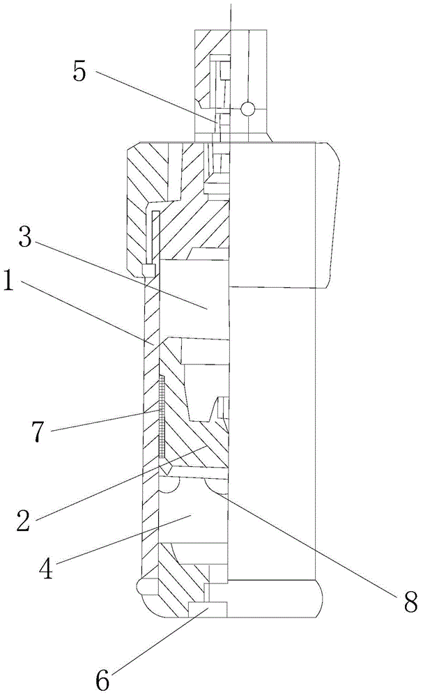
[0013] Such as figure 1 The shown piston accumulator includes a housing 1 and a piston 2. The piston 2 is located inside the housing 1 and divides the cavity in the housing 1 into an air chamber 3 and an oil chamber 4. The top of the housing 1 is provided with an air port 5, the bottom of the housing 1 is provided with an oil inlet and outlet 6, the piston 2 and the inner wall of the housing 1 are provided with a matching sliding block 7, and the piston 2 is close to the side of the oil chamber 4 The end is provided with a rubber scraper 8.
[0014] The material of the rubber scraper 8 is nitrile rubber.
[0015] A sealing strip is arranged inside the sliding block 7 .
Embodiment 2
[0017] Such as figure 1 The shown piston accumulator includes a housing 1 and a piston 2. The piston 2 is located inside the housing 1 and divides the cavity in the housing 1 into an air chamber 3 and an oil chamber 4. The top of the housing 1 is provided with an air port 5, the bottom of the housing 1 is provided with an oil inlet and outlet 6, the piston 2 and the inner wall of the housing 1 are provided with a matching sliding block 7, and the piston 2 is close to the side of the oil chamber 4 The end is provided with a rubber scraper 8.
[0018] The material of the rubber scraper 8 is butyl rubber.
[0019] A sealing strip is arranged inside the sliding block 7 .
Embodiment 3
[0021] Such as figure 1 The shown piston accumulator includes a housing 1 and a piston 2. The piston 2 is located inside the housing 1 and divides the cavity in the housing 1 into an air chamber 3 and an oil chamber 4. The top of the housing 1 is provided with an air port 5, the bottom of the housing 1 is provided with an oil inlet and outlet 6, the piston 2 and the inner wall of the housing 1 are provided with a matching sliding block 7, and the piston 2 is close to the side of the oil chamber 4 The end is provided with a rubber scraper 8.
[0022] The material of the rubber scraper 8 is fluorine rubber.
[0023] A sealing strip is arranged inside the sliding block 7 .
[0024] The invention has longer service life, better oil and gas isolation effect, and the oil liquid is not easily oxidized. The viscosity of the working oil used by the components is 10 ~ 100cSt. When the oil temperature is low, the hydraulic oil with low viscosity can be selected.
PUM
 Abstract
Description
Claims
Application Information
 - R&D
- Intellectual Property
- Life Sciences
- Materials
- Tech Scout
- Unparalleled Data Quality
- Higher Quality Content
- 60% Fewer Hallucinations
Browse by: Latest US Patents, China's latest patents, Technical Efficacy Thesaurus, Application Domain, Technology Topic, Popular Technical Reports.
© 2025 PatSnap. All rights reserved.Legal|Privacy policy|Modern Slavery Act Transparency Statement|Sitemap|About US| Contact US: help@patsnap.com