Supercharge Your Innovation With Domain-Expert AI Agents!

Metal machining scrap iron recovery device based on magnetic attraction principle

A metal processing and recycling device technology, applied in metal processing equipment, metal processing mechanical parts, manufacturing tools, etc., can solve the problems of increasing labor intensity, easily damaged cutting tools, and increasing work intensity.

Inactive Publication Date: 2020-10-30
广州一纪电子商务有限公司
View PDF0 Cites 3 Cited by
  • Summary
  • Abstract
  • Description
  • Claims
  • Application Information

AI Technical Summary

Problems solved by technology

[0003] The processing of metal parts includes simple grinding, drilling, etc., and the objects need to be clamped and positioned before processing, especially in the mass production and manufacturing process of some large factories. At the same time, during the production process, cutting will generate a lot of waste. And some smaller cutting workpieces, these will fall under the cutting platform, which will bring a lot of inconvenience to normal production activities, increase the work intensity and reduce the work efficiency. At the same time, the temperature of the cutting tool will gradually rise when it works for a long time High, very easy to damage the cutting tool; when traditional metal cutting equipment cuts metal products, iron filings often splash and accumulate on the bottom plate of the cutting equipment. The iron filings generated during cutting are recycled again, which undoubtedly greatly increases the labor intensity
[0004] Therefore, we proposed a metal processing iron filings recycling device based on the principle of magnetic attraction. Through the built-in magnetic attraction components, the iron filings generated during hardware cutting are collected, avoiding the traditional metal cutting equipment, which does not have the ability to recover iron filings function; solves the problem of iron filings splashing when cutting with traditional metal cutting equipment

Method used


Image

  • Metal machining scrap iron recovery device based on magnetic attraction principle
  • Metal machining scrap iron recovery device based on magnetic attraction principle
  • Metal machining scrap iron recovery device based on magnetic attraction principle

Examples


Embodiment Construction

[0033] The technical solutions in the embodiments of the present invention will be clearly and completely described below in conjunction with the accompanying drawings in the embodiments of the present invention. Obviously, the described embodiments are only a part of the embodiments of the present invention, rather than all the embodiments. Based on the embodiments of the present invention, all other embodiments obtained by those of ordinary skill in the art without creative work shall fall within the protection scope of the present invention.

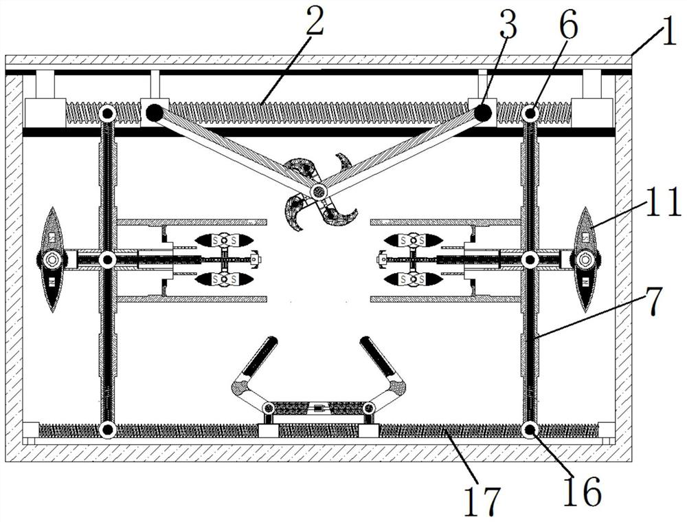
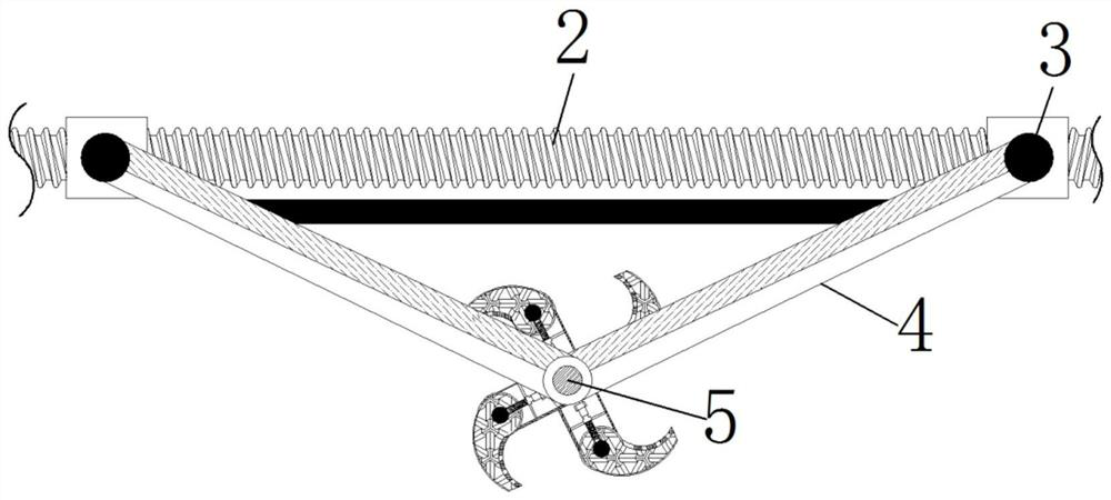
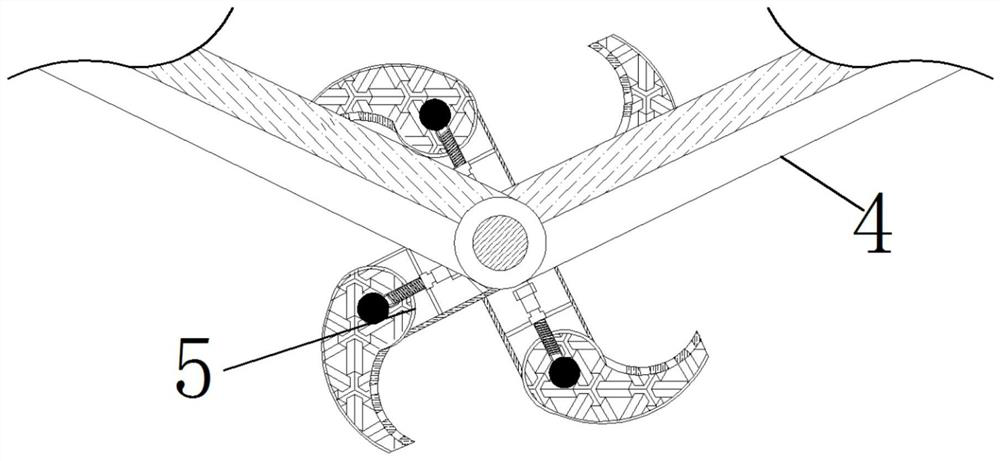
[0034] See Figure 1-12 , A metal processing iron scrap recovery device based on the principle of magnetic attraction, comprising an equipment main body 1 inside which is provided with a drive screw 2, and the outer side of the drive screw 2 is threadedly connected with a thread block 3, the thread A shaft 4 is movably connected to the outside of the block 3, and a cutting knife 5 is movably connected to the end of the shaft 4 away from ...


PUM


Abstract

The invention relates to the technical field of metal machining, and disclosed is a metal machining scrap iron recovery device based on a magnetic attraction principle. The device comprises an equipment body, a driving screw is arranged in the equipment body, the outer side of the driving screw is in threaded connection with threaded blocks, and the outer sides, perpendicular to connecting screws,of bearing blocks are movably connected with bearing screws. One end of each bearing screw is movably connected with a magnetic gear, the outer side of each magnetic gear is movably provided with a permanent magnet, the other end of each bearing screw is movably connected with a mounting assembly, and the end, away from the corresponding bearing screw, of each mounting assembly is movably connected with a water spraying opening. The upper and lower sides of each mounting assembly are movably connected with connectors, and the ends, away from the mounting assemblies, of the connectors are movably connected with electromagnets. According to the metal machining scrap iron recovery device based on the magnetic attraction principle, cooling water is sprayed from the water spraying openings, cutting knives are cooled, and the situation that the temperature of the cutting knives is too high after long-time cutting and accordingly the service life of the cutting knives is affected is avoided.

Description

Technical field [0001] The invention relates to the technical field of metal processing, in particular to a metal processing iron filings recovery device based on the principle of magnetic attraction. Background technique [0002] Hardware: Traditional hardware products, also called small hardware, refer to five metals of gold, silver, copper, iron and tin. After manual processing, they can be made into knives, swords and other artworks or metal devices. Hardware in modern society is more extensive, such as Hardware tools, hardware parts, daily-use hardware, construction hardware and security products, etc. [0003] The processing of metal parts includes simple grinding, drilling, etc. The object needs to be clamped and positioned before processing, especially in the mass production manufacturing process of some large factories, and during the production process, cutting will generate a lot of waste As well as some smaller cutting workpieces, these will fall under the cutting plat...

Claims


Application Information

Patent Timeline
Patent Type & Authority Applications(China)
IPC IPC(8): B23Q11/00B23Q11/10
CPCB23Q11/0064B23Q11/10
Inventor 欧阳莹
Owner 广州一纪电子商务有限公司
Features
  • R&D
  • Intellectual Property
  • Life Sciences
  • Materials
  • Tech Scout
  • Unparalleled Data Quality
  • Higher Quality Content
  • 60% Fewer Hallucinations
Learn More