Oil fume check valve for range hood

A range hood and check valve technology, applied in the direction of oil fume removal, application, valve lift, etc., can solve the problems of returning smoke and smell, poor sealing, etc., and achieve the effects of preventing odor leakage, low cost, and simple structure

Inactive Publication Date: 2015-03-11
王伟刚
View PDF7 Cites 5 Cited by
  • Summary
  • Abstract
  • Description
  • Claims
  • Application Information

AI Technical Summary

Problems solved by technology

[0005] In order to solve the problem of poor sealing performance of the existing oil fume check valve, resulti

Method used


Image

  • Oil fume check valve for range hood
  • Oil fume check valve for range hood
  • Oil fume check valve for range hood

Examples


specific Embodiment approach 1

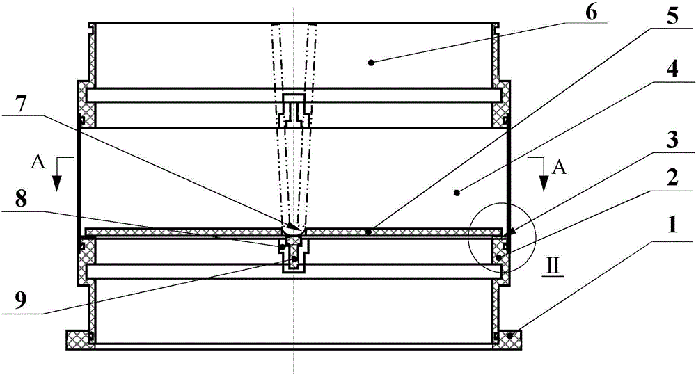
[0012] Specific implementation mode one: as Figure 1~4 As shown, the oil fume check valve for range hoods in this embodiment includes an installation interface 1, a housing and two flaps 5, and the oil fume check valve also includes a sealing layer 3, a support beam 9, two single The degree of freedom flexible hinge 7 and two support beam interfaces 8, the shell is composed of the upper shell 6, the middle shell 4 and the lower shell 2, the upper shell 6, the middle shell 4 and the lower shell 2 from top to bottom The bottom of the lower shell 2 is covered with an installation interface 1, and the inner wall of the lower shell 2 is symmetrically provided with two support beam interfaces 8, and the two ends of the support beam 9 are overlapped on the two support beam interfaces 8. , each flap 5 is connected to the side of the support beam 9 through a single-degree-of-freedom flexible hinge 7, the outer edges of the two flaps 5 overlap the upper end surface of the lower shell 2...

specific Embodiment approach 2

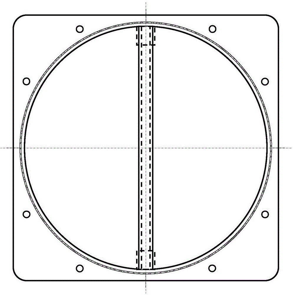
[0013] Specific implementation mode two: as image 3 As shown, in this embodiment, 3 to 6 arc-shaped grooves are evenly distributed along the circumferential direction on the outer walls of the upper shell 6 and the lower shell 2, and the inner walls of the upper and lower ends of the middle shell 4 are machined along the circumferential direction. There are protrusions corresponding to the arc grooves. Designed in this way, it is easy to connect and easy to install. Other components and connections are the same as those in the first embodiment.

specific Embodiment approach 3

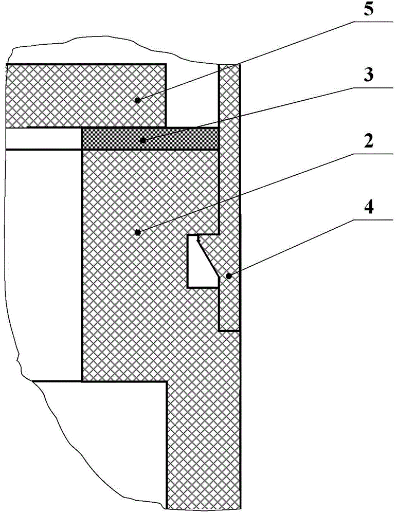
[0014] Specific implementation mode three: as Figure 4 As shown, in this embodiment, the flap 5 and the support beam 9 are seamlessly connected through the single-degree-of-freedom flexible hinge 7 to form a non-detachable whole. With such a design, the support beam 9 is seamlessly connected with the flap 5, which avoids the phenomenon of aftertaste. Other compositions and connections are the same as those in Embodiment 1 or 2.


PUM


Abstract

The invention discloses an oil fume check valve for a range hood, relates to an oil fume check valve, and solves the problem of smoke and smell return due to poor tightness of a traditional oil fume check valve. A shell of the oil fume check valve is in a combined type, and can be conveniently mounted between the range hood and a smoke discharge port; two symmetric support beam joints are arranged on the lower section of the shell, and are connected with a turning plate and a support beam; a turning plate movement mechanism is used for performing the seamless connection for the turning plate and the support beam through a unidirection flexible hinge to form a whole incapable of being disassembled; a continuous sealing layer is arranged between a sealing surface at the edge of the turning plate and a positioning surface on the shell; one end surface of the sealing layer is bonded with the positioning surface on the shell; the other end surface of the sealing layer and the turning plate form a dynamic sealing contact surface; the dynamic sealing contact surface is made to be a coupling surface according to the surface shape of the turning plate; and the dynamic sealing is finished through precise opening/closing actions of the turning plate. The oil fume check valve is used for a smoke discharge pipe of the range hood.

Description

technical field [0001] The invention relates to an oil fume check valve, in particular to an oil fume check valve used for a range hood. Background technique [0002] At present, the oil fume check valve is composed of an installation interface, a housing and a flap mechanism installed in the housing. When the airflow pushes the flap to open the airflow channel, the airflow enters the flue through the shell. When the airflow stops, the flap is seated under the action of gravity or spring resilience, and the reverse airflow channel is blocked, so that the odor of the reverse airflow can be eliminated. Enter the room connected to the other side of the flap through the shell, which is the basic function of the oil fume check valve. [0003] In order to block the flow of reverse air flow, the key technology of this structure is to ensure the effective sealing between the flap and the housing after the flap is seated. The tightness requirements should be very strict. [0004] ...

Claims


Application Information

Patent Timeline
IPC IPC(8): F16K15/03
CPCF16K15/036F16K1/226F16K27/0218F24C15/20
Inventor 王伟刚
Owner 王伟刚
Why Eureka
Try Eureka