
Air-conditioning control method

A control method and air-conditioning technology, applied in the direction of control input involving air characteristics, space heating and ventilation control input, heating and ventilation control system, etc., can solve problems such as indoor temperature fluctuations, long response time, and long time required. To achieve the effect of control, precise control and high energy efficiency

Active Publication Date: 2015-03-11
GREE ELECTRIC APPLIANCES INC
View PDF4 Cites 34 Cited by
  • Summary
  • Abstract
  • Description
  • Claims
  • Application Information

AI Technical Summary

Problems solved by technology

However, when the fuzzy control method plus PID control method is used for control, the system response time is longer when the whole machine is running.
Today, when people pursue a high-comfort life, this control method cannot be precisely controlled, and it takes a long time to achieve stability, and the whole machine needs a lot of experiments or experience when setting control parameters.
[0004] Based on the above description, a new air-conditioning control method is urgently needed to solve the problems in the prior art that the system response time is long when the whole machine is running, the control cannot be accurately controlled, and the external fan and expansion valve opening linkage control system has a long stabilization time. Easy to fluctuate, air conditioner control frequency changes rapidly with indoor working conditions, causing indoor temperature fluctuations and poor comfort, and the whole machine needs a lot of experiments or experience when formulating control parameters

Method used


Image

  • Air-conditioning control method
  • Air-conditioning control method
  • Air-conditioning control method

Examples


Embodiment Construction

[0037] In order to make the technical problems solved by the present invention, the technical solutions adopted and the technical effects achieved clearer, the technical solutions of the embodiments of the present invention will be further described in detail below in conjunction with the accompanying drawings. Obviously, the described embodiments are only the technical solutions of the present invention. Some, but not all, embodiments. Based on the embodiments of the present invention, all other embodiments obtained by those skilled in the art without creative efforts fall within the protection scope of the present invention.

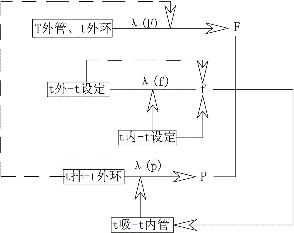
[0038] The present application provides an air conditioner control method, the control method comprising steps:

[0039] S1. Real-time detection of the temperature T of the outer pipe of the outdoor unit 外管 , Outdoor ambient temperature T 外环 And the compressor discharge temperature T when the air conditioner is running 排 , and bring the detected val...


PUM


Abstract

The invention relates to the field of air-conditioning operational control and specifically relates to an air-conditioning control method. The air-conditioning control method comprises the steps of S1, detecting the outer tube temperature T-outer tube of an outdoor unit, an outdoor environment temperature T-outdoor environment and the exhaust temperature T-exhaust of a compressor in real time and obtaining the real-time operational rotating speed of the outdoor unit according to the operational rotating speed function of the outdoor fan; S2, detecting an indoor environment temperature T-indoor in real time, and taking the indoor environment temperature T-indoor and the door environment temperature T-outdoor environment into a compressor operational frequency function to obtain the real-time operational frequency of the compressor; and S3, detecting an inner tube temperature T-inner tube of an indoor unit and n suction temperature T-suction of the compressor, and taking the inner tube temperature T-inner tube, the suction temperature T-suction of the compressor, the outdoor environment temperature T-outdoor environment and the exhaust temperature T-exhaust of the compressor into an expansion valve openness degree function to obtain the openness degree of the expansion valve. According the air-conditioning control method, the system response time of the whole unit is short, the air-conditioning unit can enter a steady operation stage rapidly, precise control can be achieved, and the number of early matching experiments is small.

Description

technical field [0001] The invention relates to the field of air conditioner operation control, in particular to an air conditioner control method. Background technique [0002] With the improvement of people's living standards, people rely more and more on air conditioners. Many families or offices use air conditioners for heating in winter or cooling in summer. Generally, in the prior art, most air conditioners use the collected temperature and other parameters to control the operating frequency of the compressor, the opening of the expansion valve, the components of the four-way valve, and the speed of the internal and external units to realize the functions of cooling and heating. The logical response speed realizes the stability of indoor environment comfort. [0003] In the prior art, when the air conditioner is running, the operating frequency of the compressor, the opening of the expansion valve, the components of the four-way valve, and the speed of the internal an...

Claims


Application Information

Patent Timeline
IPC IPC(8): F24F11/00
CPCF24F11/30F24F11/70F24F2110/00F24F2110/10F24F2110/12
Inventor 罗永前熊军吴俊鸿魏广飞
Owner GREE ELECTRIC APPLIANCES INC
Learn More