Measuring method for pseudo code delay of spread spectrum signal with high dynamic range and low signal-to-noise ratio

A low signal-to-noise ratio, spread-spectrum signal technology, used in measurement devices, radio wave measurement systems, instruments, etc., can solve the problem that the pseudo-code loop cannot achieve a stable tracking state, the pseudo-code delay is difficult to measure quickly and accurately, and the DLL It takes a long time for the loop to stabilize, and achieves the effect of high-precision open-loop estimation, improved carrier synchronization performance, and easy engineering implementation.

Inactive Publication Date: 2015-03-11
INST OF ELECTRONICS ENG CHINA ACAD OF ENG PHYSICS
View PDF2 Cites 34 Cited by
  • Summary
  • Abstract
  • Description
  • Claims
  • Application Information

AI Technical Summary

Problems solved by technology

On the one hand, high dynamics and low signal-to-noise ratio bring great challenges to the carrier tracking of spread spectrum signals
On the other hand, the measurement accuracy and speed of pseudo-code delay are a pair of mutually restrictive factors. The smaller the bandwidth of the DLL loop, the higher the measurement accuracy of pseudo-code delay, and the long...

Method used


Image

  • Measuring method for pseudo code delay of spread spectrum signal with high dynamic range and low signal-to-noise ratio
  • Measuring method for pseudo code delay of spread spectrum signal with high dynamic range and low signal-to-noise ratio
  • Measuring method for pseudo code delay of spread spectrum signal with high dynamic range and low signal-to-noise ratio

Examples


Embodiment Construction

[0027] The present invention proposes a method for measuring the pseudo code time delay of a high dynamic low signal-to-noise ratio spread spectrum signal, which can realize fast and high-precision measurement of the pseudo code time delay in a complex environment. The specific implementation plan is as follows:

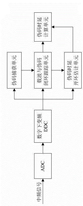
[0028] The overall implementation block diagram of the spread spectrum receiver is as follows figure 1 Shown. The spread spectrum receiver samples the intermediate frequency analog signal by ADC, and obtains the baseband complex signal r(k)=I(k)+jQ(k) through digital down-conversion. The baseband complex signal is simultaneously output to the pseudo code acquisition unit, the carrier and pseudo code closed loop tracking unit, and the pseudo code time delay open loop estimation unit.

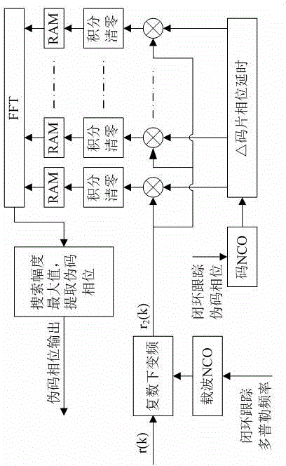
[0029] The pseudo code acquisition unit uses a partially matched filter FFT algorithm to perform a two-dimensional time-frequency search on the baseband complex signal, and perform detectio...


PUM


Abstract

The invention discloses a measuring method for pseudo code delay of a spread spectrum signal with high dynamic range and low signal-to-noise ratio. A spread spectrum receiver is used for performing ADC (Analog to Digital Converter) sampling on an intermediate frequency analog signal; the intermediate frequency analog signal is subjected to digital downconversion to obtain a baseband complex signal r(k)=I(k)+jQ(k); the baseband complex signal is simultaneously outputted to a pseudo code capturing unit, a carrier and pseudo code closed-loop tracking unit and a pseudo code time delay open-loop estimation unit; the carrier and pseudo code closed-loop tracking unit is used for tracking carrier frequency and pseudo code phase according to the captured doppler frequency and pseudo code phase information; a pseudo code time delay measuring pulse is used for outputting the doppler frequency and the pseudo code phase information to the pseudo code time delay open-loop estimation unit and outputting the pseudo code phase information to a pseudo code time delay calculation unit; the pseudo code time delay calculation unit is used for correcting closed-loop tracking measurement data of the pseudo time delay by using the open-loop estimation result and realizing quick high-precision measurement of the pseudo time delay. By the adoption of the method, the quick high-precision measurement of the pseudo time delay in the complex environment can be realized.

Description

Technical field [0001] The invention relates to the technical field of spread spectrum system time difference positioning, and specifically to a method for measuring the pseudo code time delay of a spread spectrum signal with high dynamics and low signal to noise ratio. Background technique [0002] Time difference positioning, also known as hyperbolic positioning, is a passive positioning technology. It uses the time difference between the target signal's arrival at multiple receiving stations and determines the target's position according to the principle of hyperboloid intersection. Spread spectrum system time difference positioning system has the characteristics of good concealment and high positioning accuracy, and has obtained rapid development and wide application. The key is to quickly and accurately measure the pseudo-code delay. [0003] The author, Yang Jingchao, published a journal document titled “Research on High-precision Time Delay Measurement Technology Based on ...

Claims


Application Information

Patent Timeline
IPC IPC(8): G01S5/02
CPCG01S5/02
Inventor 贺寓东马国宁王明解楠季战领
Owner INST OF ELECTRONICS ENG CHINA ACAD OF ENG PHYSICS
Why Eureka
Try Eureka