Supercharge Your Innovation With Domain-Expert AI Agents!

Arrangement method of engine TMAP (Air Temperature and Manifold Absolutely Pressure) sensor

An arrangement method and engine technology, which are applied in the fields of instruments, special data processing applications, electrical digital data processing, etc., can solve the problems of laboriousness, unreasonable placement of TMAP sensors, and analysis of the rationality of TMAP sensor placement, so as to save material costs. , the effect of improving R&D efficiency

Active Publication Date: 2015-03-11
CHERY AUTOMOBILE CO LTD
View PDF1 Cites 3 Cited by
  • Summary
  • Abstract
  • Description
  • Claims
  • Application Information

AI Technical Summary

Problems solved by technology

However, the location of the TMAP sensor is unreasonable, which has a great impact on its signal detection.
At present, in the development process of automobile engines, computer fluid dynamics (CFD) technology is rarely used to analyze the rationality of TMAP sensor placement. Because it is difficult to determine the flow conditions inside the engine intake manifold during the test, it is difficult for the designer to determine the root cause of the problem

Method used


Image

  • Arrangement method of engine TMAP (Air Temperature and Manifold Absolutely Pressure) sensor
  • Arrangement method of engine TMAP (Air Temperature and Manifold Absolutely Pressure) sensor
  • Arrangement method of engine TMAP (Air Temperature and Manifold Absolutely Pressure) sensor

Examples


Embodiment Construction

[0016] Combine below Figure 1 to Figure 10 , the present invention is described in further detail.

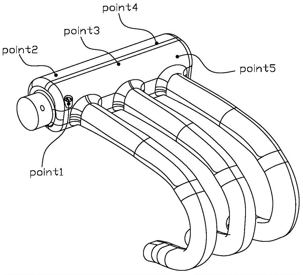
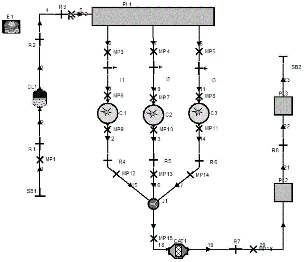
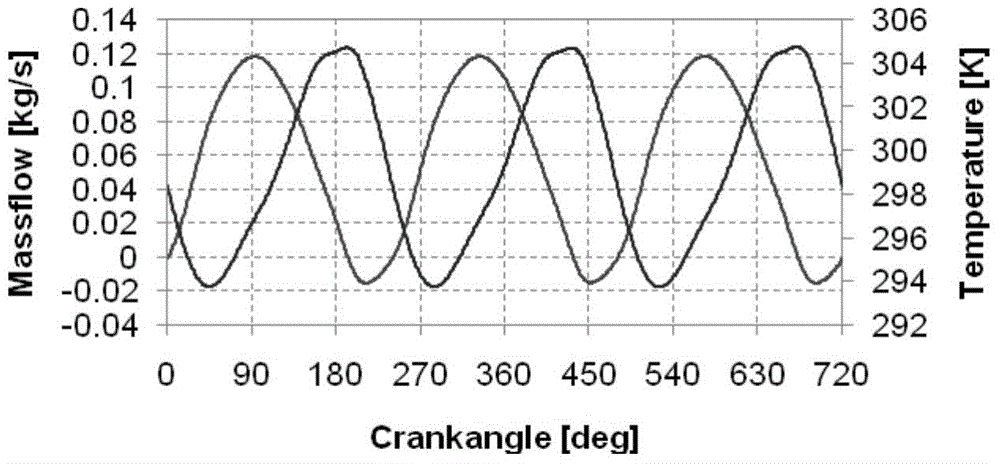
[0017] refer to Figure 10 , a method for arranging TMAP sensors of an engine, comprising the steps of: (A) collecting geometric models of an engine intake manifold, and grouping and meshing the geometric models; (B) obtaining intake manifold The periodic transient boundary conditions of each inlet and outlet of the pipe; (C) Apply the periodic transient boundary conditions in step B to the grid model obtained in step A and perform iterative calculation; (D) find out the pressure according to the calculation results The point or area of ​​most stable variation is used to place the TMAP sensor. The basic idea of ​​this method is to replace the original continuous field of physical quantities in the space and time coordinates with a set of values ​​of a series of finite discrete points, and to establish the relationship between the variable values ​​at these discrete points th...


PUM


Abstract

The invention belongs to the technical field of automobile engine development, and particularly relates to an arrangement method of an engine TMAP (Air Temperature and Manifold Absolutely Pressure) sensor. The arrangement method comprises the following steps: (A) collecting geometric models of an engine intake manifold, and grouping and meshing the geometric models; (B) calculating according to engine one-dimensional thermodynamics to obtain periodic transient boundary conditions of each inlet and outlet; (C) applying the periodic transient boundary conditions in the step B to the meshed models obtained by the step A and then performing iterative calculation; (D) discovering a point or a region with the most stable pressure change for arranging the TMAP sensor according to the calculation result. Through the steps, the best TMAP sensor arrangement position can be analyzed before trial production of a sample; meanwhile, effect comparison of different arrangement positions can also be performed. The research and development efficiency is improved and a large amount of material cost is reduced.

Description

technical field [0001] The invention belongs to the technical field of automobile engine development, in particular to a method for arranging an engine TMAP sensor. Background technique [0002] The engine TMAP sensor is one of the important sensors on the car. It detects the air pressure and temperature in the intake manifold, and is used to correct the fuel injection amount of the engine to ensure the normal operation of the engine. However, the location of the TMAP sensor is unreasonable, which has a great impact on its signal detection. At present, in the development process of automobile engines, computer fluid dynamics (CFD) technology is rarely used to analyze the rationality of TMAP sensor placement. Because it is difficult to determine the flow inside the engine's intake manifold during testing, it is difficult for designers to determine the root cause of the problem. Contents of the invention [0003] The purpose of the present invention is to provide a method ...

Claims


Application Information

Patent Timeline
Patent Type & Authority Applications(China)
IPC IPC(8): G06F17/50
Inventor 徐亚飞陶丽芳
Owner CHERY AUTOMOBILE CO LTD
Features
  • R&D
  • Intellectual Property
  • Life Sciences
  • Materials
  • Tech Scout
  • Unparalleled Data Quality
  • Higher Quality Content
  • 60% Fewer Hallucinations
Learn More