X wave band over-mode relativistic klystron amplifier

A relativistic and X-band technology, applied in the field of X-band over-mode relativistic klystron amplifiers, can solve the problems of reduced radial size of devices, inability to generate high-power X-band microwaves, and reduced power capacity

Active Publication Date: 2015-03-11
NORTHWEST INST OF NUCLEAR TECH
View PDF2 Cites 21 Cited by
  • Summary
  • Abstract
  • Description
  • Claims
  • Application Information

AI Technical Summary

Problems solved by technology

When it works in a high frequency band such as the X-band, due to the reduction in the radial size of the device, the power capacity is reduced, and it is impossible to generate high-power X-band microwaves

Method used


Image

  • X wave band over-mode relativistic klystron amplifier
  • X wave band over-mode relativistic klystron amplifier
  • X wave band over-mode relativistic klystron amplifier

Examples


Embodiment Construction

[0011] The X-band overmodulated RKA of the present invention will be described in detail below in conjunction with the accompanying drawings and embodiments.

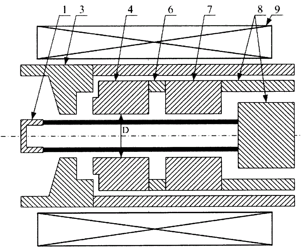
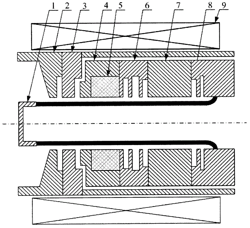
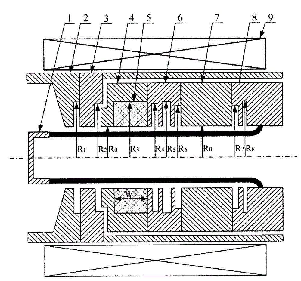
[0012] Such as figure 2 As shown, the present invention provides an X-band overmode relativistic klystron amplifier comprising: ring cathode 1, resonant reflector 2, input cavity 3, first drift tube 4, wave-absorbing material 5, cluster cavity 6, the first Two-stage drift tube 7, output cavity 8 and magnetic field coil 9. The annular cathode is located at the forefront of the structure, and emits an annular relativistic electron beam under the action of a high-voltage pulse; the resonant reflector, the input cavity, the first drift tube, the absorbing material, the cluster cavity, and the second drift tube and the output cavity are sequentially placed on the rear side of the annular cathode; the magnetic field coil is installed on the periphery of the entire structure.

[0013] The working mode of the resonant reflec...


PUM


Abstract

The invention discloses an X wave band over-mode relativistic klystron amplifier, which comprises an annular cathode, a resonant reflector, an input cavity, a first section of drift tube, a wave absorbing material, a buncher cavity, a second section of drift tube, an output cavity and a magnetic field coil, wherein the annular cathode is arranged at the most significant end of the structure and emits annular relativistic electron beams outwards under the action of high voltage pulse, the resonant reflector, the input cavity, the first section of drift tube, the wave absorbing material, the buncher cavity, the second section of drift tube and the output cavity are sequentially arranged at rear of the annular cathode, the magnetic field coil is installed at the periphery of the whole structure, the working mode of the resonant reflector, the input cavity, the buncher cavity and the output cavity is a TM02 mode, and the first section of drift tube and the second section of drift tube can transmit a TM01 mode. The X wave band over-mode relativistic klystron amplifier can produce high power X wave band microwave.

Description

technical field [0001] The invention belongs to the field of microwave masers, in particular to an X-band overmode relativistic klystron amplifier. Background technique [0002] The relativistic klystron amplifier (RKA) has the characteristics of controllable output microwave frequency and phase, and is suitable for power combination. It is one of the most potential high-power microwave devices at present. The RKA working mode of traditional technology is TM 01 mode, which passes through the drift tube to the TM 01 Mode cut-off, that is, requires R / λ<0.385 (where R is the radius of the drift tube, and λ is the microwave wavelength), to realize the isolation between the cavities. Such as figure 1 As shown, a traditional technique of RKA is given. It includes an annular cathode 1 , an input chamber 3 , a first-stage drift tube 4 , a cluster chamber 6 , a second-stage drift tube 7 , an output chamber 8 and a magnetic field coil 9 . When working, the annular cathode 1 em...

Claims


Application Information

Patent Timeline
Patent Type & Authority Applications(China)
IPC IPC(8): H01J25/22
CPCH01J25/22
Inventor 肖仁珍陈昌华邓昱群李佳伟白现臣宋志敏范菊平曹亦兵
Owner NORTHWEST INST OF NUCLEAR TECH
Why Eureka
Try Eureka