End pressure type coaxial load

A coaxial load and coaxial technology, used in electrical components, circuits, waveguide devices, etc., can solve the problems of increasing signal transmission distance, deformation of large insulators, low signal transmission efficiency, etc. Effects of Burratio, Good Index and Stability

Inactive Publication Date: 2015-03-11
安徽蓝麦通信股份有限公司
View PDF5 Cites 5 Cited by
  • Summary
  • Abstract
  • Description
  • Claims
  • Application Information

AI Technical Summary

Problems solved by technology

[0002] Currently, threaded installation structures are used for microwave loads, such as figure 2 As shown, the resistor 7 is installed in the hole at the tail of the pin 8, the large insulator 9 and the small insulator 10 are respectively installed on the pin 8, and then they are installed together in the cavity 101, and the shell 102 is fixed to the On the external thread of the cavity 101; this structure has four major disadvantages: first, the power is small, easy to overload, the cavity 101 is not provided with heat dissipation fins, and the resistance 7 is easy to generate heat when used, which cannot be discharged in time, and it is used for a long time Cause the product to ignite, burn out, and be scrapped; its electrical performance is poor, and its working frequency band is low. The transmission efficiency of the product is extremely low, and the double-extreme structure increases the transmission distance of the signal in the solid medium. Due to the principle that the longer the transmission distance of the signal in the insulator, the lower the working frequency band

Method used


Image

  • End pressure type coaxial load
  • End pressure type coaxial load

Examples


Embodiment

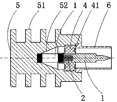
[0016] Example: Combined figure 1 , the end-pressure coaxial load of this embodiment includes: it includes a columnar resistor 1 that realizes the conversion of microwave power to heat energy of the product, a compression spring 2 that can still be in good contact after long-term use of the product, an inner conductor 3, and supports Functional insulating medium 4, outer conductor 5 to realize product grounding and heat dissipation, and end face bushing 6;

[0017] figure 1 As shown, a heat sink 51 is arranged on the outer circumference of the outer conductor 5 to improve the power carrying capacity of the product; a coaxial tapered transmission cavity 52 is arranged inside the outer conductor 5 to realize the gradual transition of signal transmission and reduce the reflection ratio of the signal, thereby reducing The voltage standing wave ratio of the product realizes high-efficiency signal transmission; the impedance compensation ring 41 provided on both sides of the insu...


PUM


Abstract

The invention discloses an end pressure type coaxial load. The end pressure type coaxial load comprises a cylindrical resistor, a compressed spring, an inner conductor, an insulating medium and an outer conductor which are coaxially arranged, as well as an end face shaft sleeve, wherein a compressed spring and a resistor hole are formed in the tail of the inner conductor; the cylindrical resistor is cylindrical; the two ends of the cylindrical resistor are sintered with silver resistors, and the other part of the cylindrical resistor is sintered with a thick-film resistor; the insulating medium is of a circle structure; the single side of the insulating medium is cut off through a seamless cutting technology, and impedance compensation rings are arranged on the both sides; the end face shaft sleeve is positioned at the top part of the outer conductor, used for positioning the insulating medium, the inner conductor and the cylindrical resistor, and meanwhile participates in transmission of electrical performance; cooling fins are arranged on the outer periphery of the outer conductor; a coaxial step type conical transmission cavity is defined inside the outer conductor. The end pressure type coaxial load disclosed by the invention is simple in structure, stable and reliable in properties, high in signal transmission efficiency, high in working frequency band, simple to assemble, easy to operate, and suitable for large batch production.

Description

technical field [0001] The invention relates to an end pressure coaxial load. Background technique [0002] Currently, threaded installation structures are used for microwave loads, such as figure 2 As shown, the resistor 7 is installed in the hole at the tail of the pin 8, the large insulator 9 and the small insulator 10 are respectively installed on the pin 8, and then they are installed together in the cavity 101, and the shell 102 is fixed to the On the external thread of the cavity 101; this structure has four major disadvantages: first, the power is small, easy to overload, the cavity 101 is not provided with heat dissipation fins, and the resistance 7 is easy to generate heat when used, which cannot be discharged in time, and it is used for a long time Cause the product to ignite, burn out, and be scrapped; its electrical performance is poor, and its working frequency band is low. The transmission efficiency of the product is extremely low, and the double-extreme st...

Claims


Application Information

Patent Timeline
IPC IPC(8): H01P1/26
Inventor 齐磊
Owner 安徽蓝麦通信股份有限公司
Why Eureka
Try Eureka