
Climbing type steel wire rope ladder

A steel wire rope and climbing technology, which is applied in the field of tools with secondary protection function, can solve the problems that the upper end of the aluminum alloy hanging ladder cannot be fixed, and the labor intensity and operation risk of high-altitude operators are high.

Inactive Publication Date: 2015-03-11
STATE GRID CORP OF CHINA +1
View PDF12 Cites 2 Cited by
  • Summary
  • Abstract
  • Description
  • Claims
  • Application Information

AI Technical Summary

Problems solved by technology

[0002] At present, the main tool for climbing up and down between the cross arm of the overhead transmission line tower and the conductor is the aluminum alloy hanging ladder. The upper end of the aluminum alloy hanging ladder is suspended on the upper and lower ends of the pole tower cross arm, and the lower end cannot be fixed. The workers at heights swing back and forth when going up and down the aluminum alloy hanging ladder. Especially in the operation of replacing synthetic insulators during power outages, a secondary protective device to prevent wires from falling off must be hung before operation. Special tools, high-altitude workers sometimes step on insulators to maintain their own balance when going up and down aluminum alloy hanging ladders and maintenance operations. During operations, high-altitude workers must not only maintain their own balance, but also carry out maintenance and acceptance operations at high altitudes. The labor intensity of high-altitude workers and job risk

Method used


Image

  • Climbing type steel wire rope ladder
  • Climbing type steel wire rope ladder

Examples


Embodiment Construction

[0017] The climbing type wire rope ladder of the present invention comprises stirrup type pedal 4, rope ladder main wire rope 3 and wire hook 8 etc. The main wire rope 3 of the rope ladder is evenly inserted into a stirrup type pedal 3 every 40cm distance from the upper end to the lower end.

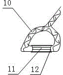
[0018] Stirrup type pedal 4 is inserted on the rope ladder main wire rope 3 by the upper end wire rope of its pedal wire rope cover 10, and pedal steel wire rope cover 10 is wound and fixed on the rope ladder main wire rope 3 by iron binding wire 5. The general 400mm of the circumference of described pedal wire rope cover 10.

[0019] Have upper U-shaped ring 1 on the upper end wire rope cover 2 of rope ladder main wire rope 4, the lower end wire rope cover 7 of rope ladder main wire rope 4 is connected with lead hook 9 by following U-shaped ring 6. The general 300mm of the circumference of described upper end wire rope cover 2, the general 200mm of the circumference of lower end wire r...


PUM


Abstract

The invention discloses a climbing type steel wire rope ladder and solves the aerial work problem of difficulty in climbing up and down between an overhead transmission line pole tower cross arm and a conducting wire. The climbing type steel wire rope ladder comprises a plurality of stirrup type pedals, a main rope ladder steel wire rope and a conducting wire hook, wherein the stirrup type pedals are inserted into the main rope ladder steel wire rope through upper-end steel wire ropes of pedal steel wire rope sleeves; the pedal steel wire rope sleeves are fixedly arranged on the main rope ladder steel wire rope; an upper end steel wire rope sleeve and a lower end steel wire rope sleeve are respectively inserted into the two ends of the main rope ladder steel wire rope; an upper U-shaped ring is arranged on the upper end steel wire rope sleeve in a sleeving way; the lower end steel wire rope sleeve is connected with the conducting wire hook through a lower U-shaped ring. The climbing type steel wire rope ladder has the benefits that the climbing type steel wire rope ladder is not limited by an overhead transmission line pole tower type when in use, is easily operated, is convenient to carry, is practical and flexible, is safe and reliable in field operation, can be operated by one person and has a secondary protection function of preventing the conducting wire to fall off; the high-altitude operation labor intensity and the work and operation risk of operation personnel on a tower are reduced, the working efficiency is improved, and the field operation cost is lowered.

Description

technical field [0001] The invention relates to a climbing rope ladder, in particular to a tool for high-altitude climbing operation between the cross arm of an overhead power transmission line tower and a conductor, and also has a secondary protection function of preventing the conductor from falling off during maintenance operations. Background technique [0002] At present, the main tool for climbing up and down between the cross arm of the overhead transmission line tower and the conductor is the aluminum alloy hanging ladder. The upper end of the aluminum alloy hanging ladder is suspended on the upper and lower ends of the pole tower cross arm, and the lower end cannot be fixed. The workers at heights swing back and forth when going up and down the aluminum alloy hanging ladder. Especially in the operation of replacing synthetic insulators during power outages, a secondary protective device to prevent wires from falling off must be hung before operation. Special tools, ...

Claims


Application Information

Patent Timeline
IPC IPC(8): H02G1/02A63B27/00
Inventor 张涛王正波王军王飞刘海军丁明
Owner STATE GRID CORP OF CHINA
Learn More