DC power transmission system traveling wave protection method

A technology of DC transmission system and traveling wave protection, applied in emergency protection circuit devices, electrical components, etc., can solve problems such as inability to accurately grasp fault information, and achieve the effect of quickly and accurately judging faults and avoiding risks

Active Publication Date: 2015-03-11
XUJI GRP +2
View PDF4 Cites 6 Cited by
  • Summary
  • Abstract
  • Description
  • Claims
  • Application Information

AI Technical Summary

Problems solved by technology

[0004] The purpose of the present invention is to provide a traveling wave protection method for DC transmission ...

Method used


Image

  • DC power transmission system traveling wave protection method
  • DC power transmission system traveling wave protection method

Examples


Embodiment Construction

[0020] The specific embodiments of the present invention will be further described below in conjunction with the accompanying drawings.

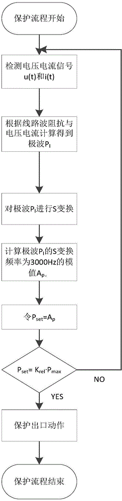
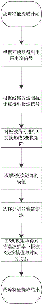
[0021] 1. First collect the line current and voltage of this station, according to the relationship P between the sampling value of the current and voltage signal and the polar wave impedance of the DC line I (t)=Z p i(t)-u(t) calculates the polar wave P I .

[0022] 2. Epipolar wave P I S-transformation is used for analysis, and the time-frequency distribution characteristics of the modulus value of polar wave S-transformation before and after the fault are obtained. The time when the sudden change is the largest is the time when the fault occurs. Calculate the modulus value Ap of the polar wave S-transformation frequency of 3000HZ as P set .

[0023] The pole wave protection judgment frequency band is the signal whose frequency distribution is 2950-3050 Hz after the fault pole wave S transformation, and generally takes the 3000 Hz sign...


PUM


Abstract

The invention relates to a DC power transmission system traveling wave protection method and belongs to the VHV DC transmission technology field. According to the method, a line current and a line voltage of a local station are acquired, polar waves PI are figured out, S conversion on the polar waves is carried out for analysis, time frequency distribution characteristics of polar wave S conversion module values are acquired, and time of the largest abrupt change is the fault generation time; processing is carried out according to protection criteria and protection motion strategies, the criteria are that Pset is greater than or equal to Krel*Pmax, the reliable coefficient Krel is greater than 1, the Pmax is the largest value of polar wave S conversion module values of all outer-zone faults and disturbance, moreover, a polar wave setting value acquired through the formula above is obviously smaller than a first peak value of inner-zone fault polar wave S conversion module values, so no error protection motion generation is not only guaranteed during outer-zone faults, but also inner-zone protection motion is guaranteed to be reliable. The DC power transmission system traveling wave protection method can rapidly and accurately determine the faults and avoids line traveling wave protection error motion.

Description

technical field [0001] The invention relates to a traveling wave protection method for a direct current transmission system, which belongs to the technical field of ultra-high voltage direct current transmission. Background technique [0002] After a fault occurs on a HVDC transmission line, its voltage and current usually contain a wealth of non-power frequency transient components, and the fault component varies with different fault conditions such as fault time, fault location, transition resistance, and system operating conditions. Variety. Therefore, effective analysis of fault transient signals and extraction of corresponding fault feature information are of great significance for rapid action of system protection, accurate identification of fault types, and rapid location of fault points. [0003] Power system transient signals are typical non-stationary signals. In traditional signal processing, Fourier transform establishes the connection between the signal time do...

Claims


Application Information

Patent Timeline
IPC IPC(8): H02H7/26
Inventor 黄金海宁联辉吴庆范张爱玲曹森张绍军罗磊田培涛付艳范子强许朋见
Owner XUJI GRP
Why Eureka
Try Eureka