Synchronous rectification drive circuit and television set

A drive circuit and synchronous rectification technology, applied in the field of electronics, can solve the problems of low circuit conversion efficiency and so on

Active Publication Date: 2015-03-11
SHENZHEN SKYWORTH RGB ELECTRONICS CO LTD +1
View PDF9 Cites 6 Cited by
  • Summary
  • Abstract
  • Description
  • Claims
  • Application Information

AI Technical Summary

Problems solved by technology

and figure 1 The first delay circuit 102 and the second delay circuit 103 in the shown synchronous rectification drive circuit can meet the conduction requirements of the high-side power device N11 and the low-side power device N12 under the worst condition and in a wide range (i.e. longer dead time), figure 1 Although the synchronous rectification drive circuit shown can realize the alternate conduction of the high-side power device N11 and the low-side power device N12 to achieve the purpose of normal operation, however, due to figure 1 The first delay circuit 102 and the second delay circuit 103 of the synchronous rectification driving circuit shown cannot be adaptively adjusted (that is, the dead time is fixed), therefore, under different loads, figure 1 The dead time of the synchronous rectification driving circuit shown does not change, so that the conversion efficiency of the circuit is low; and, figure 1 The first delay circuit 102 and the second delay circuit 103 in the synchronous rectification drive circuit shown are generally composed of digital circuits, that is, various transmission gate circuits (such as NOT gates, NAND gates, and NOR gates, etc.) ), because the delay of the transmission gate is relatively small, the first delay circuit 102 and the second delay circuit 103 need to be composed of a plurality of transmission gates in logical series, thus making the circuit structure more complex and the circuit layout area also increased large, which in turn makes the cost of the circuit higher

Method used


Image

  • Synchronous rectification drive circuit and television set
  • Synchronous rectification drive circuit and television set
  • Synchronous rectification drive circuit and television set

Examples


Embodiment Construction

[0039] It should be understood that the specific embodiments described here are only used to explain the present invention, not to limit the present invention.

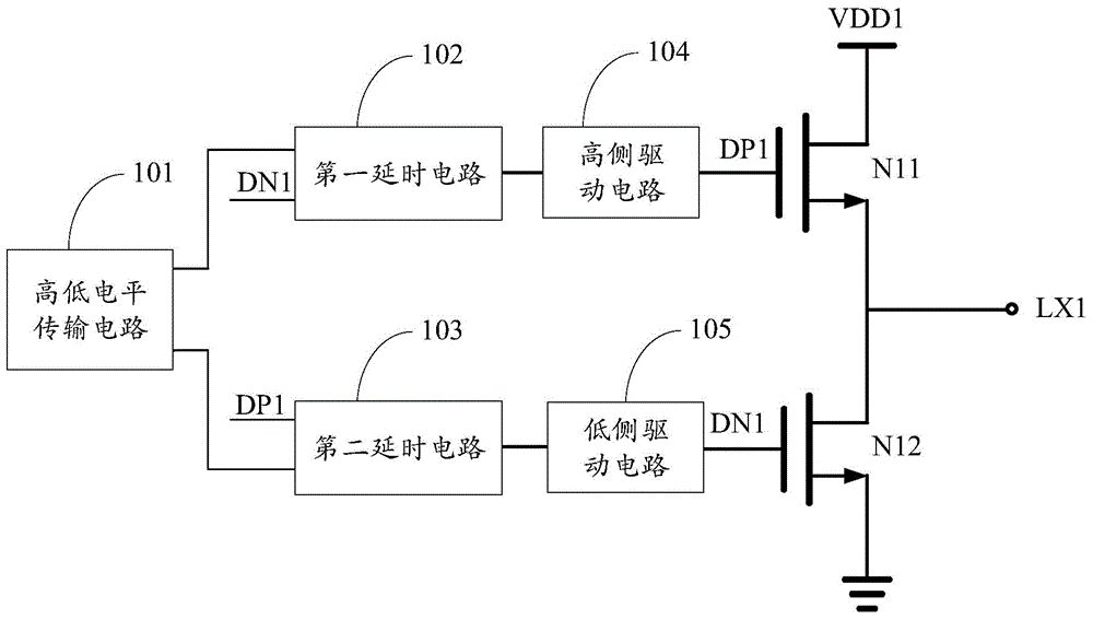
[0040] The invention provides a synchronous rectification drive circuit.

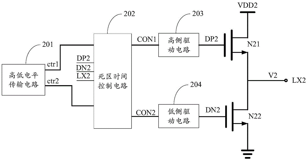
[0041] refer to figure 2 , figure 2 It is a schematic diagram of the module structure of an embodiment of the synchronous rectification driving circuit of the present invention.

[0042] In this embodiment, the synchronous rectification drive circuit includes a working voltage input terminal VDD2, a high-low level transmission circuit 201, a dead time control circuit 202, a high-side drive circuit 203, a low-side drive circuit 204, a high-side power device N21, a low-side Side power device N22 and synchronous rectification output terminal LX2.

[0043] Wherein, the first output end of the high-low level transmission circuit 201 is connected to the input end of the high-side driving circuit 203 through the dead time control circuit 202, and...


PUM


Abstract

The invention discloses a synchronous rectification drive circuit which includes a high-low level transmission circuit, a dead time control circuit, a high side drive circuit, a low side drive circuit, a high side power device and a low side powder device and a synchronous rectification output end. The high-low level transmission circuit outputs a first high-low level signal and a second high-low level signal. The dead time control circuit controls first dead time between turning off the high side power device and turning on the low side powder device according to the drive signal of the high side power device and the signal of the synchronous rectification output end, controls second dead time between turning off the low side power device and turning on the high side power device according to the drive signal and the drive voltage signal of the low side power device, outputs a first control signal to the high side drive circuit, and outputs a second control signal to the low side drive circuit. The high side drive circuit outputs the drive signal of the high side power device according to the first control signal. The low side drive circuit outputs the drive signal of the low side power device according to the second control signal. By the synchronous rectification drive circuit, rectification efficiency is increased.

Description

technical field [0001] The invention relates to the field of electronic technology, in particular to a synchronous rectification drive circuit and a television. Background technique [0002] The power conversion circuit of DC output usually needs to use a rectification circuit with rectification function, and the rectification circuit generally uses a rectification diode, and because the rectification diode itself has a large conduction voltage drop, the efficiency of the rectification circuit is low . Synchronous rectification technology is to use the power device MOSFET (also called MOS tube) as a rectifier device to replace the rectifier diode. Since the on-resistance of the MOS tube is very small (about tens of milliohms to hundreds of milliohms), even if the The current is large, and the voltage drop of the MOS tube is relatively small, so that the power loss of the rectifier circuit is less, thereby improving the efficiency of the rectifier circuit. [0003] The MOS ...

Claims


Application Information

Patent Timeline
Patent Type & Authority Applications(China)
IPC IPC(8): H02M7/217
Inventor 王卫田姚森宝滕谋艳杨智昌
Owner SHENZHEN SKYWORTH RGB ELECTRONICS CO LTD
Why Eureka
Try Eureka