An uplink transmit power control method and device and a base station

A transmission power control and transmission power technology, which is applied in the field of communication, can solve problems such as the reduction of received signal SINR, the decline of decoding accuracy of base stations, and the interference of other users.

Active Publication Date: 2018-07-31
DATANG MOBILE COMM EQUIP CO LTD
View PDF3 Cites 0 Cited by
  • Summary
  • Abstract
  • Description
  • Claims
  • Application Information

AI Technical Summary

Problems solved by technology

[0007] The present invention provides an uplink transmission power control method, device and a base station to solve the problem that the current uplink transmission power control method causes the SINR of the signal received by the base station side to decrease, the decoding accuracy of the base station to decrease, and cause interference to other users The problem

Method used


Image

  • An uplink transmit power control method and device and a base station
  • An uplink transmit power control method and device and a base station
  • An uplink transmit power control method and device and a base station

Examples


Embodiment 1

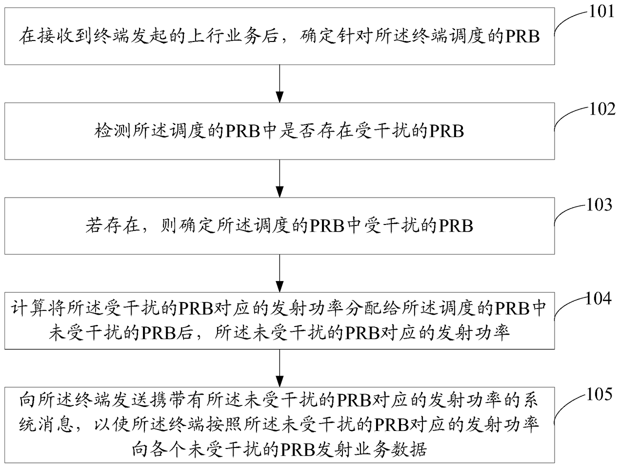
[0068] refer to figure 1 , shows a flow chart of an uplink transmission power control method according to Embodiment 1 of the present invention. The method may include the steps of:

[0069] Step 101, after receiving an uplink service initiated by a terminal, determine a PRB scheduled for the terminal.

[0070] After accessing the base station, the terminal can interact with the base station for uplink services and downlink services. After receiving the uplink service initiated by the terminal, the base station first determines the PRB scheduled for the terminal, that is, determines which resources the terminal will use to perform the uplink service.

[0071] Step 102, detecting whether there is an interfered PRB among the scheduled PRBs.

[0072] During the initial scheduling process, the scheduled resources are normal, but as the environment changes, the scheduled resources will also change, such as being affected by interference or frequency selective fading, which will ...

Embodiment 2

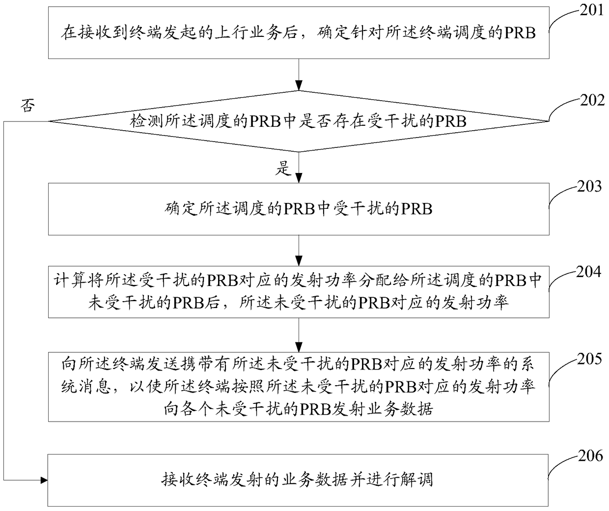
[0083] refer to figure 2 , shows a flowchart of an uplink transmit power control method according to Embodiment 2 of the present invention. The method may include the steps of:

[0084] Step 201, after receiving an uplink service initiated by a terminal, determine a PRB scheduled for the terminal.

[0085] A base station is a form of a radio station, which refers to a radio transceiver station that transmits information to and from a terminal through a mobile communication switching center in a certain radio coverage area. If a terminal needs to perform services, it first needs to access a base station, communicate with the terminal through the base station it accesses, and provide services for the terminal.

[0086] After receiving the uplink service initiated by the terminal, the base station first determines the PRB of the PUSCH (Physical Uplink Shared Channel, Physical Uplink Shared Channel) scheduled for the terminal, that is, determines which resources the terminal wi...

Embodiment 3

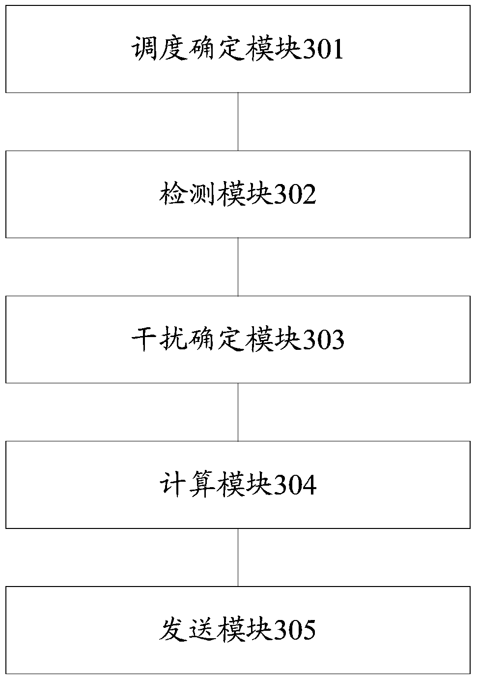
[0142] refer to image 3 , shows a structural block diagram of an uplink transmit power control device according to Embodiment 3 of the present invention. The device can include the following modules:

[0143] A scheduling determination module 301, configured to determine a physical resource block PRB scheduled for the terminal after receiving the uplink service initiated by the terminal;

[0144] A detection module 302, configured to detect whether there is an interfered PRB among the scheduled PRBs;

[0145] An interference determination module 303, configured to determine the interfered PRB among the scheduled PRBs when the detection result of the detection module is present;

[0146] A calculation module 304, configured to calculate the transmit power corresponding to the undisturbed PRB after the transmit power corresponding to the interfered PRB is allocated to the undisturbed PRB among the scheduled PRBs;

[0147] The sending module 305 is configured to send a system...


PUM


Abstract

The invention provides an uplink transmission power control method, an uplink transmission power control device and a base station. The method includes the following steps that: after uplink services initiated by a terminal are received, PRBs (Physical Resource Block) for the scheduling of the terminal are determined; whether interfered PRBs exist in the PRBs for the scheduling is detected; if interfered PRBs exist in the PRBs for the scheduling, the interfered PRBs in the PRBs for the scheduling are determined; transmission power corresponding to un-interfered PRBs is calculated after transmission power corresponding to the interfered PRBs is allocated for the un-interfered PRBs in the PRBs for the scheduling; and a system message carrying the transmission power corresponding to the un-interfered PRBs is transmitted to the terminal, so that the terminal can transmit service data to the un-interfered PRBs according to the transmission power corresponding to the un-interfered PRBs. With the uplink transmission power control method, device and base station of the invention adopted, the SINR of data receiving of the base station side can be improved, and the decoding accuracy of the base station can be ensured, and interference to other users can be reduced.

Description

technical field [0001] The present invention relates to the field of communication technology, in particular to an uplink transmission power control method, device and base station. Background technique [0002] LTE (Long Term Evolution, Long Term Evolution) is a long-term evolution of the UMTS (Universal Mobile Telecommunications System, Universal Mobile Telecommunications System) technical standard formulated by the 3GPP (The 3rd Generation Partnership Project, Third Generation Partnership Project). The LTE system introduces key transmission technologies such as OFDM (Orthogonal Frequency Division Multiplexing) and MIMO (Multi-Input Multi-Output), which significantly increases spectrum efficiency and data transmission rate, and supports A variety of bandwidth allocations, and supports global mainstream 2G / 3G frequency bands and some new frequency bands, so the spectrum allocation is more flexible, and the system capacity and coverage are also significantly improved. [00...

Claims


Application Information

Patent Timeline
Patent Type & Authority Patents(China)
IPC IPC(8): H04W52/14
CPCH04W52/146
Inventor 陆松鹤王金宝
Owner DATANG MOBILE COMM EQUIP CO LTD
Why Eureka
Try Eureka