
Vehicle control device

A technology for a control device and a vehicle, which is applied to the control device, electrical control, vehicle components, etc., can solve the problems of reduced deceleration, unease, and discomfort of the driver, and achieve the effect of extending the driving distance and reducing fuel consumption.

Inactive Publication Date: 2015-03-11
TOYOTA JIDOSHA KK
View PDF6 Cites 10 Cited by
  • Summary
  • Abstract
  • Description
  • Claims
  • Application Information

AI Technical Summary

Problems solved by technology

On the other hand, during the execution of the inertial running control, the power transmission path between the engine and the drive wheels is cut off during running as described above, so the so-called engine brake is not applied, and the feeling of deceleration felt by the driver is weakened.
Therefore, in the conventional inertial running control described in the aforementioned Japanese Patent Application Laid-Open No. 2011-163535, for example, when the gradient of the traveling road changes to a downhill gradient during the execution of the control and the vehicle speed increases, there is a possibility that the Bring discomfort or uneasiness to the driver

Method used


Image

  • Vehicle control device
  • Vehicle control device
  • Vehicle control device

Examples


Embodiment Construction

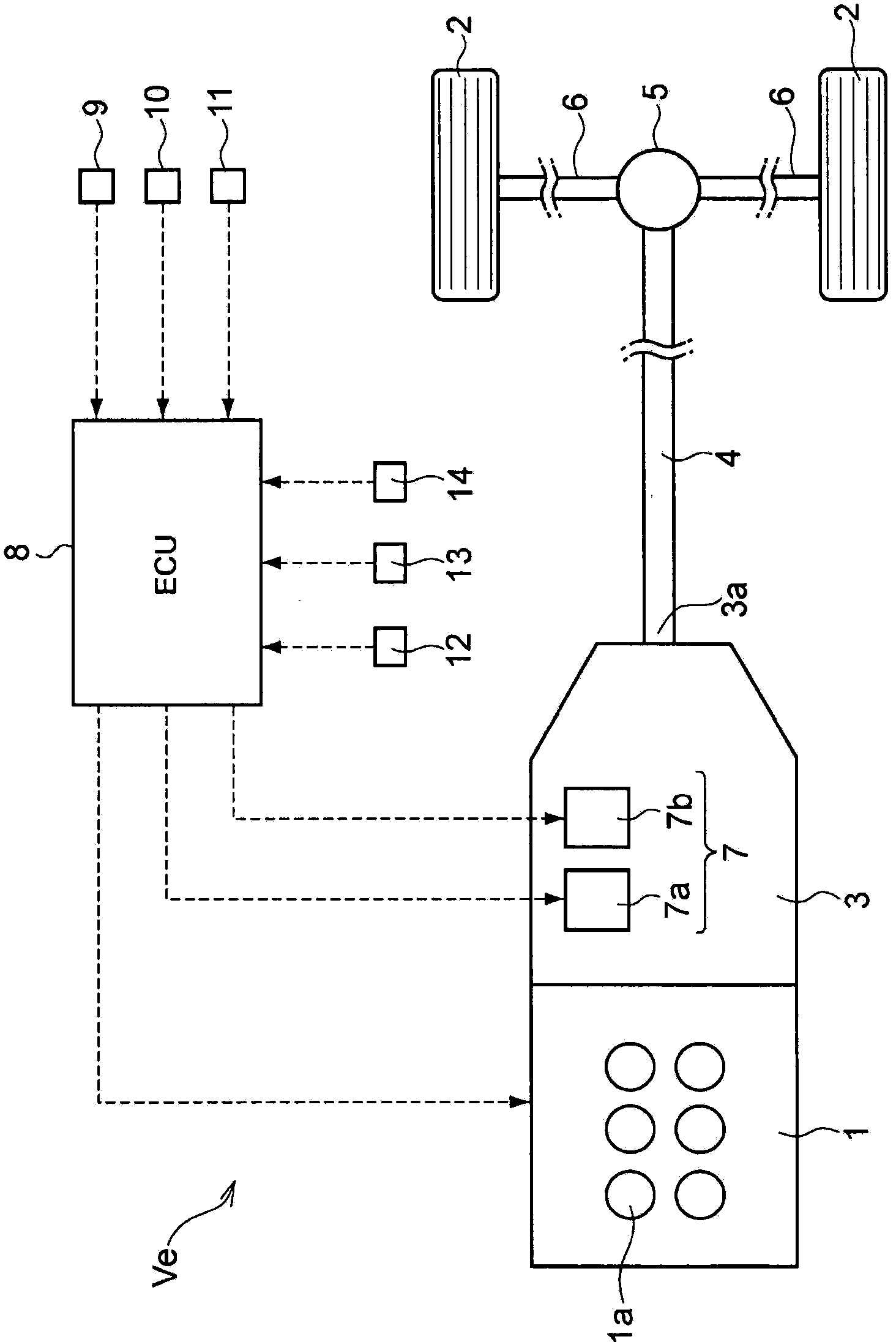
[0024] Next, the present invention will be specifically described with reference to the drawings. figure 1 A drive system and a control system of a vehicle to be controlled in the present invention are shown. Should figure 1 The illustrated vehicle Ve has an engine 1 and an automatic transmission 3 connected to an output side of the engine 1 to transmit power output by the engine 1 to drive wheels 2 . Specifically, an automatic transmission 3 is provided on the output shaft side of the engine 1 , and drive wheels are connected to the propeller shaft 4 connected to the output shaft 3 a of the automatic transmission 3 via a differential gear 5 and a drive shaft 6 so that power can be transmitted. 2. Also, as mentioned above, in figure 1 In the figure, an example of the structure in which the engine 1 and the driving wheels 2, that is, the rear wheels are connected via the propeller shaft 4, that is, an example in which the vehicle Ve is a rear-wheel drive vehicle is shown, bu...

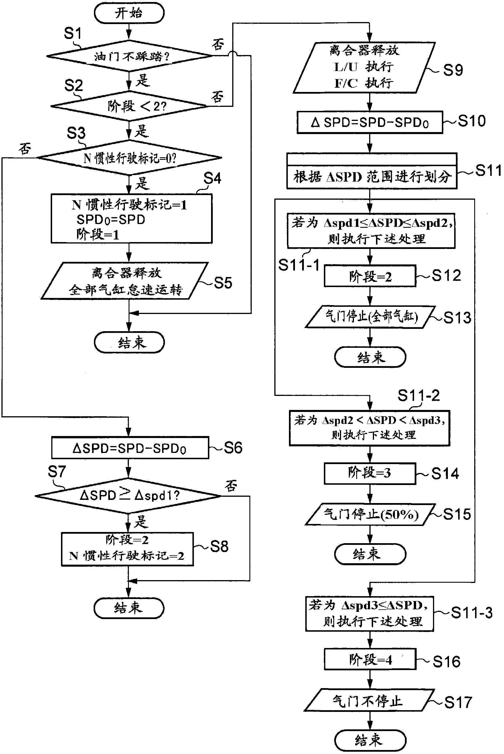
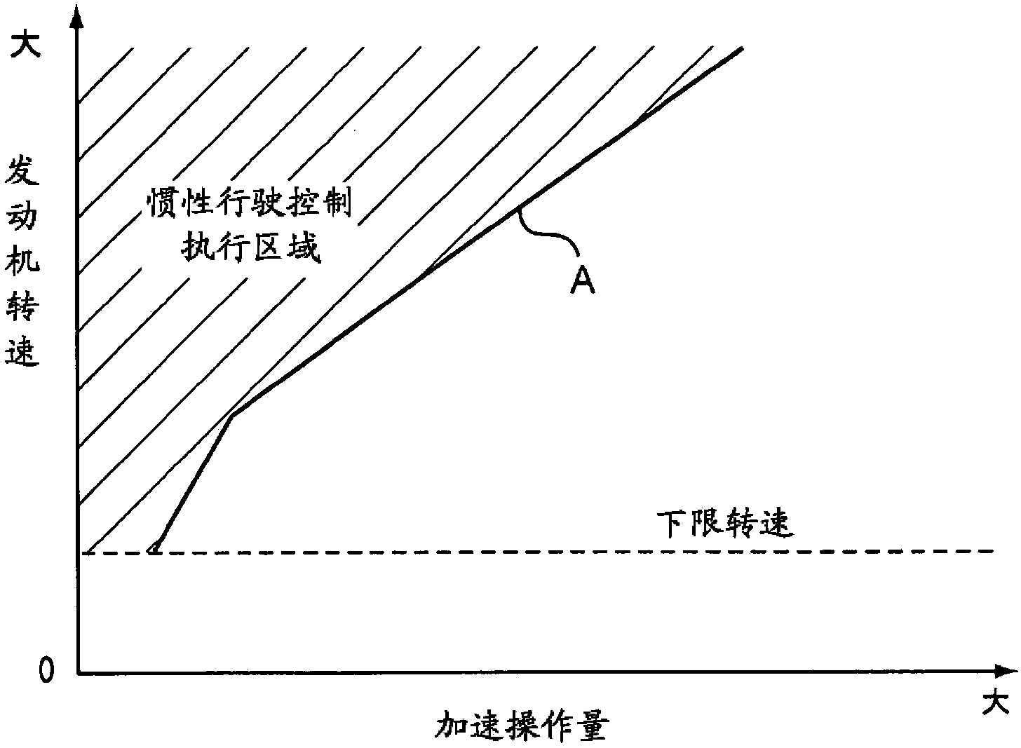

PUM


Abstract

Provided is a vehicle control device which is provided with an engine having a plurality of cylinders, a motive power transmission path for transmitting motive power between the engine and drive wheels, and a clutch mechanism for selectively connecting and disconnecting the motive power transmission path, said vehicle control device being capable of performing coasting control by disconnecting the motive power transmission path during travel to cause a vehicle to coast. The vehicle control device is provided with: a means for detecting vehicle speed; a means for detecting accelerator operation by a driver; a means for detecting the engine speed of the engine; a performing means which, in cases when accelerator operation amount during travel is returned to a prescribed operation amount or less, controls the engine such that the engine speed becomes an idling engine speed which is less than the engine speed during travel when coasting control is not being performed, and releases the clutch mechanism and disconnects the motive power transmission path to perform coasting control; and a suspending means which, when coasting control is being performed, in cases when the vehicle speed is at least a prescribed speed or the vehicle speed increases by at least a prescribed value, engages the clutch mechanism and connects the motive power transmission path, suspends the supply of fuel to the engine, and suspends the opening and closing operation of air inlet valves and exhaust valves in the plurality of cylinders.

Description

technical field [0001] The present invention relates to a control device for a vehicle having a clutch mechanism capable of selectively connecting and disconnecting a power transmission path between a driving force source and drive wheels, the control device for the vehicle being capable of releasing the clutch mechanism during travel to reduce the inertia of the vehicle drive. Background technique [0002] In recent years, for the purpose of reducing the fuel consumption of vehicles, fuel cut-off, which temporarily stops fuel supply to the engine during driving, or a state in which the vehicle is in neutral during driving, that is, a state in which the engine is disconnected from the drive system, has been carried out. Development of technologies related to so-called coasting control for vehicles coasting. The fuel cut is the following control: when the accelerator is returned to its original position during driving, that is, when the accelerator opening is fully closed, f...

Claims


Application Information

Patent Timeline
Patent Type & Authority Applications(China)
IPC IPC(8): B60W10/02B60W10/06F02D13/06F02D17/02F02D29/00F02D41/12F02D41/16F16D48/02
CPCF16D2500/50227F16D2500/5085F16D2500/3108F16D2500/3144B60W2520/10F02D41/08B60W2540/10B60W30/18072F02D2041/001B60W10/06Y02T10/48B60W10/02F16D2500/3067F02D2200/501Y02T10/42B60W2030/1809F02D2200/101F02D2200/602F02D41/0002F16D2500/10412B60W2510/0638F16D48/02F02D41/123F02D41/022F02N11/0833F02D2041/0012Y02T10/40F02D13/06F02D29/02F16D48/062F16D2500/30401F16D2500/3166F16D2500/5043F16D2500/5045F16D2500/7041Y02T10/12Y02T10/60B60W20/00B60W30/143
Inventor 光安正记
Owner TOYOTA JIDOSHA KK
Learn More