Window cleaning device

A technology of walking unit and control unit, which is applied in the field of intelligent robots, can solve the problems of misjudgment of borders, high price, easy jamming of boards or micro switches, etc., and achieve the goals of preventing misjudgment, high intelligence level, and reducing production costs Effect

Active Publication Date: 2015-03-18
ECOVACS ROBOTICS (SUZHOU ) CO LTD
View PDF10 Cites 18 Cited by
  • Summary
  • Abstract
  • Description
  • Claims
  • Application Information

AI Technical Summary

Problems solved by technology

However, this method has the following disadvantages: the window cleaning robot may be stuck on the glass frame due to no signal or the window cleaning robot cannot receive the signal due to the impact of the plate or the micro switch is easy to get stuck.
Therefore, there is such a situation: when a t The absolute value of is greater than the built-in threshold a 0 , the control unit will also make a jud

Method used


Image

  • Window cleaning device
  • Window cleaning device
  • Window cleaning device

Examples


Embodiment 1

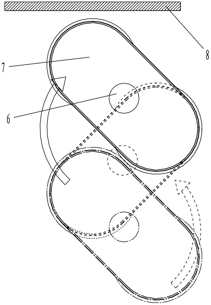
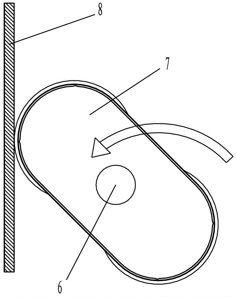
[0030] like Image 6 and Figure 7 As shown, in Embodiment 1, the traveling unit 2 is an adsorption turntable 17, and the window cleaning device 7 realizes twisting and traveling by alternately rotating the adsorption turntable. The body 16 of the window cleaning device 7 is provided with a control unit 5 , a driving unit 4 and a cleaning unit 3 . Wherein, the adsorption turntable is connected to the body 16 through a connecting piece, which can be a bearing or a central axis of rotation provided on the body, so that the adsorption turntable can be rotatably arranged at the bottom of the body 16 in various ways. For example, the adsorption turntable can be directly sleeved on its rotation center shaft, and the rotation center shaft is fixed at the bottom of the body to drive the adsorption turntable to rotate relative to the body. The adsorption turntable is, for example, made into an "I" shape, which is sleeved on the central axis of rotation. The synchronous belt is sleeve...

Embodiment 2

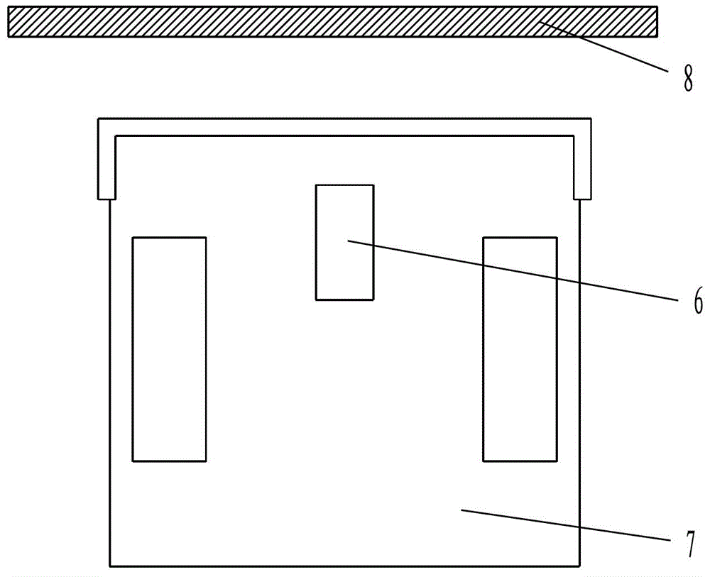
[0049] The main difference between Embodiment 2 and Embodiment 1 is that: the traveling unit 2 is a crawler belt or wheels, the window cleaning device 7 advances in a straight line, and the speed sensing unit 6 is a linear speed sensor.

[0050] like image 3 As shown, when the window cleaning device 7 is in normal operation, the body line speed of the window cleaning device 7 does not change or changes very little, and the speed value measured by the line speed sensor is v 1 ;like Figure 4 As shown, when the window cleaning device 7 hits the window frame 8, the linear velocity of the window cleaning device 7 advances to 0 in a short time. Therefore, a built-in threshold v can be preset in the control unit 0 =0 or a smaller value close to 0, the line speed sensor sends the speed value signal of the sensed real-time line speed v to the control unit 5, when v≤v 0 , the control unit 5 judges that the window cleaning device 7 has reached the frame, and the control unit 5 contr...


PUM


Abstract

The invention relates to the technical field of intelligent robots, and particularly relates to a window cleaning device. The window cleaning device comprises an adsorption unit (1), a walking unit (2), a cleaning unit (3), a driving unit (4) and a control unit (5), wherein the walking unit (2) and the cleaning unit (3) are arranged at the bottom of the window cleaning device (7); the control unit (5) is connected with the driving unit (4); the driving unit (4) is connected to the walking unit (2) and is used for driving the walking unit (2); the window cleaning device (7) further comprises a speed sensing unit (6) connected with the control unit (5); the control unit (5) controls the driving unit (4) to drive the window cleaning device (7) to stop walking or execute steering operation according to a speed value signal sent by the speed sensing unit (6). The window cleaning device disclosed by the invention can avoid a window frame in a window cleaning process and prevent mis-judgment of obstacles such as the window frame, and the production cost is lowered.

Description

technical field [0001] The invention relates to the technical field of intelligent robots, in particular to a window cleaning device. Background technique [0002] Generally, existing window-cleaning robots detect the border of framed glass mostly by hitting plates and micro switches. When the window-cleaning robot does not reach the edge of the glass, the window-cleaning robot moves normally: When the striker is pushed and the micro switch is triggered at the same time, it is considered that the window cleaning robot has reached the edge of the glass, and the window cleaning robot will retreat, so as to control the working range of the window cleaning robot. However, this method has the following disadvantages: the window cleaning robot may be stuck on the glass frame because there is no signal or the window cleaning robot cannot receive the signal due to reasons such as hitting the plate or the micro switch is easy to get stuck. [0003] In order to solve the above proble...

Claims


Application Information

Patent Timeline
IPC IPC(8): A47L1/02
Inventor 汤进举
Owner ECOVACS ROBOTICS (SUZHOU ) CO LTD
Why Eureka
Try Eureka