Self locking type elevating platform

A lifting platform, self-locking technology, applied in the field of lifting platforms, can solve the problems of inaccurate control of lifting height, large volume of hydraulic lifting platforms, complex system, etc., and achieve the effect of light weight, simple structure and stable working process

Inactive Publication Date: 2015-03-18
XIAN ZHIYUE ELECTROMECHANICAL TECH
View PDF0 Cites 3 Cited by
  • Summary
  • Abstract
  • Description
  • Claims
  • Application Information

AI Technical Summary

Problems solved by technology

The hydraulic lifting platform has the disadvantages of large volume, complicated system, difficult maintenance, and the lifting height cannot be precisely controlled.

Method used


Image

  • Self locking type elevating platform
  • Self locking type elevating platform
  • Self locking type elevating platform

Examples


Embodiment 1

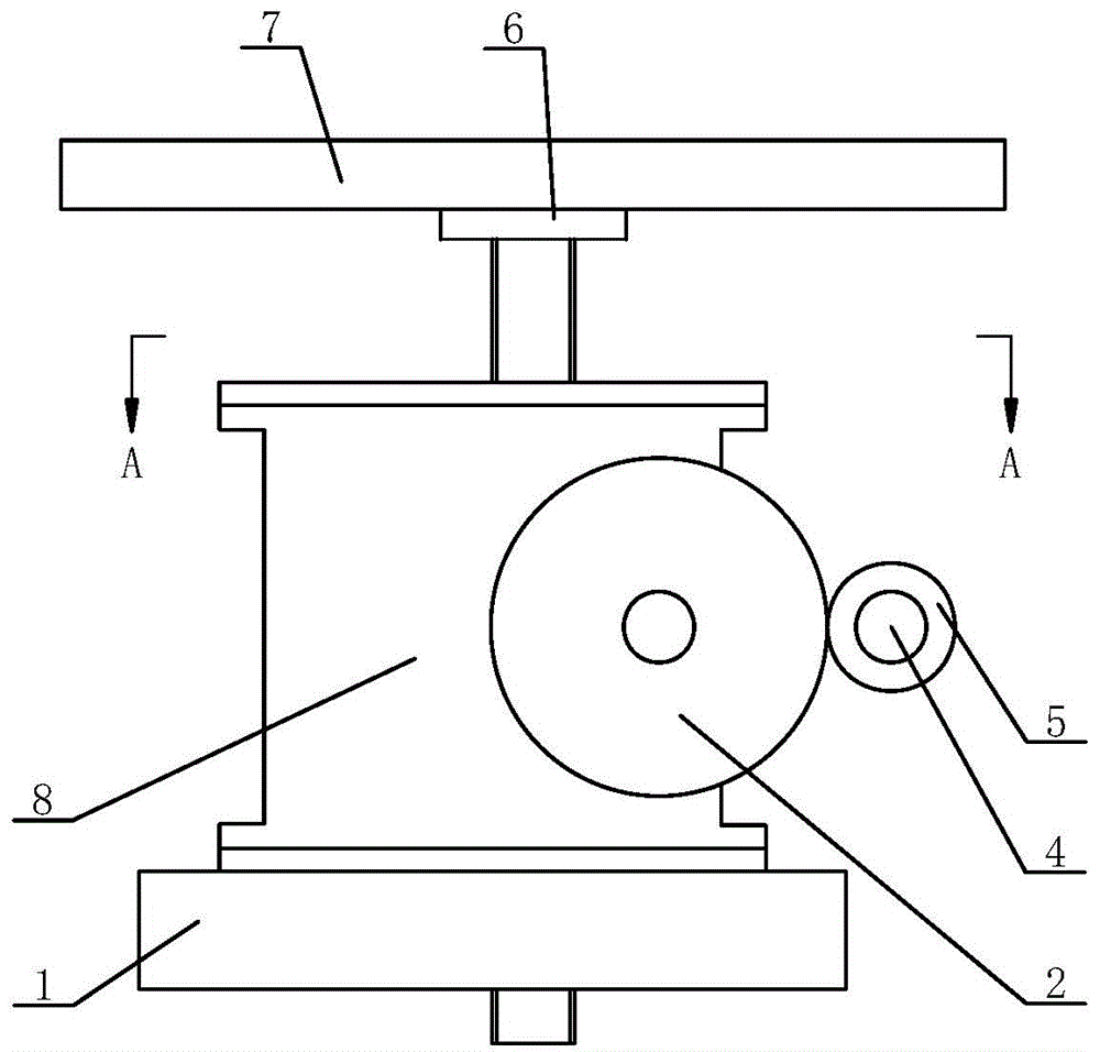
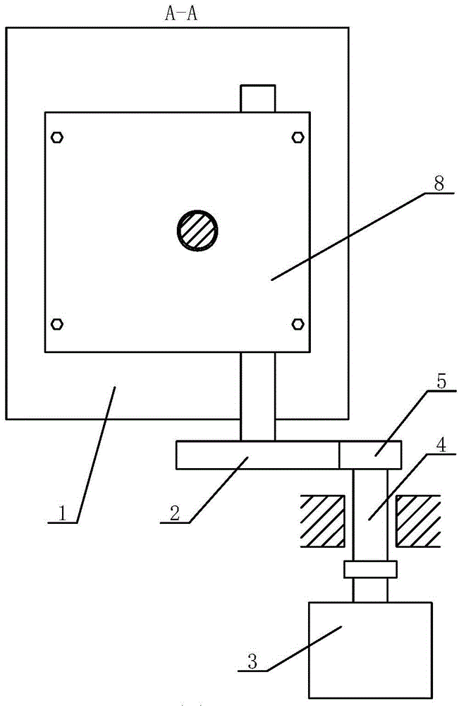
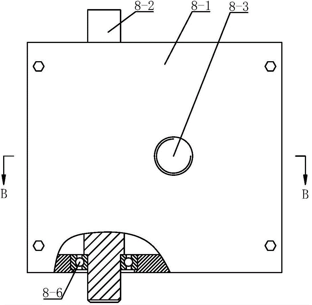
[0033] Such as Figure 1-Figure 4 As shown, the self-locking lifting platform only includes one self-locking lifting device 8 . When it works, start the drive motor 3 to rotate in the forward direction, and the drive motor 3 drives the worm 8-2 to rotate in the forward direction through the gear shaft 4, gear two 5 and gear one 2, and the worm 8-2 drives the worm gear 8 that meshes with it to form a worm gear pair -5 rotates in the forward direction, and the worm gear 8-5 drives the platen 7 to move upward through the threaded auxiliary drive screw 8-3. When the driving motor 3 reversely rotates, the platen 7 moves downward.

Embodiment 2

[0035] Such as Figure 5 with Image 6 As shown, the difference between the second embodiment and the first embodiment is that the self-locking lifting platform includes two self-locking lifting devices 8 arranged in parallel. During work, the driving motor 3 can simultaneously drive the worms 8-2 of the two self-locking lifting devices 8 to rotate forward or reversely through the gear shaft 4, the second gear 5 and the first gear 2, thereby driving the lifting of the platen 7 or drop.

Embodiment 3

[0037] Such as Figure 7 with Figure 8 As shown, the difference between the third embodiment and the first embodiment is that the self-locking lifting platform includes two self-locking lifting devices 8 arranged in series. The worms 8-2 of the two self-locking lifting devices 8 are connected by couplings. When working, the drive motor 3 can simultaneously drive the two self-locking lifting devices through the gear shaft 4, gear two 5 and gear one 2. The worm 8-2 of the device 8 rotates forward or reversely, thereby driving the lifting or lowering of the platen 7 .


PUM


Abstract

The invention discloses a self locking type elevating platform comprising a base, a drive motor and at least one self locking type elevating device driven by the drive motor. The self locking type elevating device is fixedly installed on the base, the power output shaft of the drive motor is connected to one end of a gear shaft through a coupling, a second gear is fixedly installed on the other end of the gear shaft, the first gear and the second gear are engaged to form a gear pair, the first gear is fixedly installed at the end of the power input shaft of the self locking type elevating device, and a table plate is fixedly installed at the upper end of the power output shaft of the self locking type elevating device through an installing seat. The self locking type elevating platform has the advantages that design is reasonable, structure is simple, self locking can be performed at anytime, the reliability is high, the elevating height can be controlled accurately, operation is stable, rigid impacting is avoided, the service life is long, size is small, the platform is light, transportation is facilitated, using cost is low, and the adaption range is expanded.

Description

technical field [0001] The invention relates to a lifting platform, in particular to a self-locking lifting platform. Background technique [0002] Lifting platforms emerged with people's demand for vertical transportation. The original lifting platforms used basic power methods such as manpower, animal power and water power to lift weight. Before the industrial revolution, these power methods have been widely used by lifting devices. At present, the commonly used lifting platforms are mostly driven by hydraulic pressure. The working principle is that the hydraulic oil is formed by the vane pump to a certain pressure, and passes through the oil filter, explosion-proof electromagnetic reversing valve, throttle valve, hydraulic control check valve, and balance. The valve enters the lower end of the hydraulic cylinder, so that the piston of the hydraulic cylinder moves upward to lift the heavy object. The oil returned from the upper end of the hydraulic cylinder returns to the ...

Claims


Application Information

Patent Timeline
Patent Type & Authority Applications(China)
IPC IPC(8): B66F11/04
CPCB66F11/00
Inventor 黄冰
Owner XIAN ZHIYUE ELECTROMECHANICAL TECH
Why Eureka
Try Eureka