
Chip card combination structure and method thereof

A combined structure and chip card technology, which is applied to record carriers, instruments, and electrical components used in machines, can solve the problems of troublesome production, high production costs, and time-consuming, and achieve the effect of reducing costs.

Active Publication Date: 2015-03-18
ABANCAST
View PDF11 Cites 0 Cited by
  • Summary
  • Abstract
  • Description
  • Claims
  • Application Information

AI Technical Summary

Problems solved by technology

[0002] The existing traditional chip card includes a carrier body and a chip module which are manufactured separately, and in the manufacturing process, it is necessary to make a groove on one side of the carrier body, and then insert the chip module into the groove to complete. Therefore, the production is quite troublesome and time-consuming;
[0003] At present, the chip cards circulating in the market are mainly divided into three types: ordinary SIM cards, micro SIM chips and nano SIM cards. Their sizes and sizes are different. Therefore, when the existing traditional chip cards are manufactured, only one type can be produced at a time. The size of the carrier chip and the chip module are then assembled and embedded one by one, which makes the production cost high, and the existing traditional chip card is limited by size and size, and at the same time leads to an increase in stocking costs

Method used


Image

  • Chip card combination structure and method thereof
  • Chip card combination structure and method thereof
  • Chip card combination structure and method thereof

Examples


Embodiment Construction

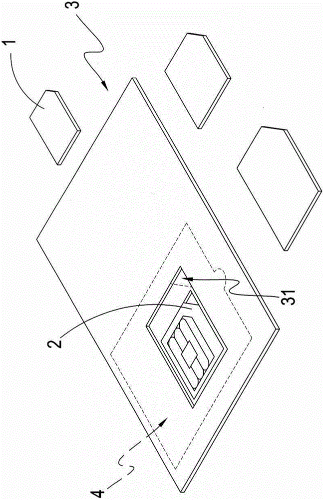
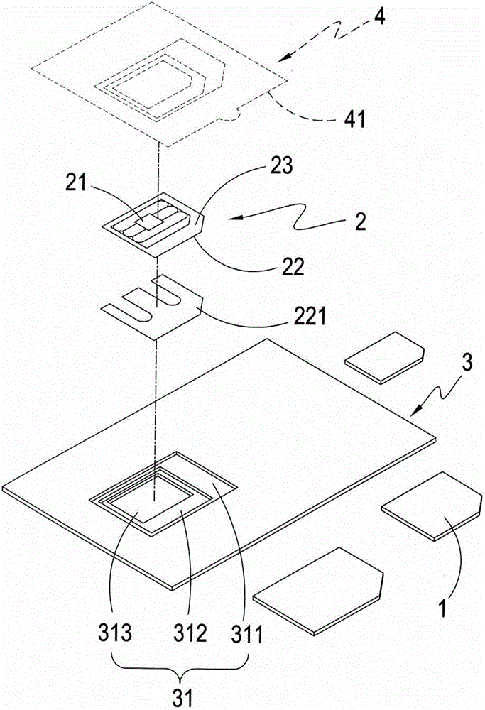
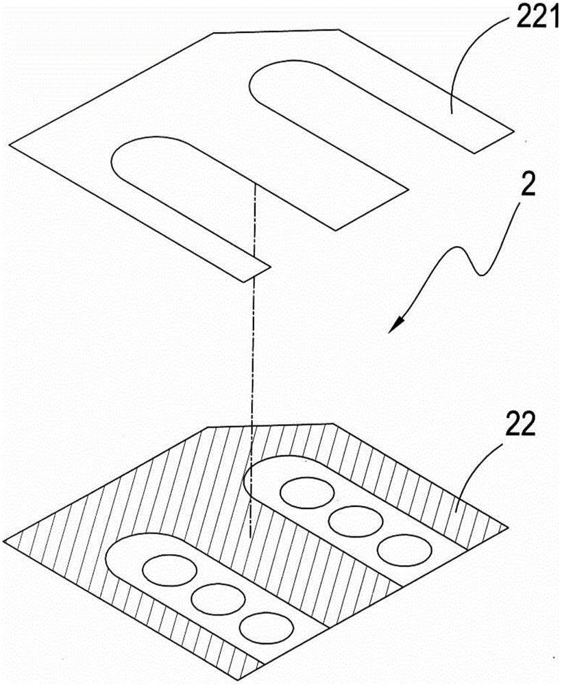
[0033] see Figure 1 to Figure 4 As shown, it is a schematic diagram of the implementation of a preferred embodiment of the present invention, a schematic diagram of separation, a schematic diagram of a thin film wafer and a schematic diagram of a fixed element. It can be clearly seen from the figure that the present invention includes at least one substrate 1, at least one fixed element 3, and at least one adhesive film 4 and at least one thin film chip 2, in this embodiment, three sizes of general SIM card, micro SIM card and nano SIM card are used as illustrations, and at least one side of the fixing element 3 is formed with at least one corresponding to the substrate 1. fixed slot 31, and the fixed slot 31 is further divided into the first fixed slot 311 (the size is equal to the size of a general SIM card), the second fixed slot 312 (the size is equal to the size of a micro SIM card) and the third fixed slot 313 (the size is equal to the size of a micro SIM card) nano SIM...


PUM


Abstract

The invention relates to a chip card combination structure and a method thereof. The chip card combination structure comprises at least one substrate, at least one fixing element, at least one adhesive film and at least one thin film chip; a fixing groove which is corresponding to the substrate is formed in a side wall of the fixing element; the adhesive film is arranged at one side of the fixing element and shields the fixing groove; and the thin film chip is arranged in the fixing groove and is bonded to the adhesive film. When the chip card combination structure is used, the adhesive film and the thin film chip can be turned over; the substrate is arranged in the fixing groove; the adhesive film and the thin film chip cover the substrate; the thin film chip is made to be combined with the substrate; and the adhesive film is turned over; the combined thin film chip and the substrate are taken out; and corresponding positions of the thin film chip and the substrate are made to be correct. With the chip card combination structure and the method thereof of the invention adopted, practical progress such as free application and production cost saving can be made.

Description

technical field [0001] The invention provides a chip card, in particular a chip card assembly structure with free application and low production cost and its method. Background technique [0002] The existing conventional chip card includes a carrier body and a chip module which are manufactured separately, and a groove needs to be made on one side of the carrier body in the manufacturing process, and then the chip module is inserted into the groove to complete. Therefore, the production is quite troublesome and time-consuming; [0003] At present, the chip cards circulating in the market are mainly divided into three types: ordinary SIM cards, micro SIM chips and nano SIM cards. Their sizes and sizes are different. Therefore, when the existing traditional chip cards are manufactured, only one type can be produced at a time. The size of the carrier chip and the chip module are then assembled and embedded one by one, so that the production cost remains high, and the applicat...

Claims


Application Information

Patent Timeline
IPC IPC(8): H01L21/673
CPCG06K19/063G06K19/07H01L21/673
Inventor 王本乐
Owner ABANCAST
Learn More