
Integral brush and vibration motor having the same

A technology of integral brush and vibration motor, applied in electric components, circuits, current collectors, etc., can solve the problem of high cost of flexible board materials, and achieve the effects of high productivity, reduced manufacturing costs, and high reliability

Inactive Publication Date: 2007-02-21
SAMSUNG ELECTRO MECHANICS CO LTD
View PDF0 Cites 0 Cited by
  • Summary
  • Abstract
  • Description
  • Claims
  • Application Information

AI Technical Summary

Problems solved by technology

Moreover, due to the complex manufacturing process involving multiple steps, the cost of flexible board materials is very high

Method used


Image

  • Integral brush and vibration motor having the same
  • Integral brush and vibration motor having the same
  • Integral brush and vibration motor having the same

Examples


Embodiment Construction

[0034] The preferred embodiments of the integral brush and the vibration motor with the brush according to the present invention will be described in detail below with reference to the accompanying drawings.

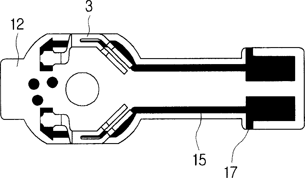
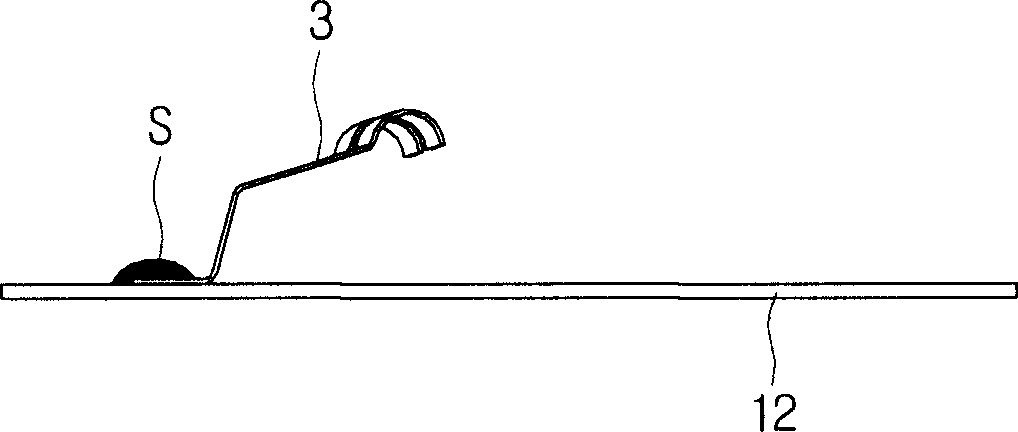
[0035] Figure 4 is a plan view of a brush according to an embodiment of the present invention, and Figure 5 yes Figure 4 Cross-sectional view of the structure. Such as Figure 4 and 5 As shown, a brush 30 according to an embodiment of the present invention includes an arm 31 and an extension 33 extending from the arm 31 .

[0036] arm 31, such as Figure 4 As shown, it has an inwardly curved shape. At one end of the arm 31, as Figure 5 As shown, there is an arc-shaped contact portion 31a. Contact portion 31a, such as Figure 6 As shown, it is in contact with the lower surface of the commutator 75 .

[0037] The arm 31 may comprise a plurality of segments 31b, 31c. Therefore, even if one segment is not in contact with the commutator, the other segment is in...


PUM


Abstract

A vibration motor and a brush for a vibration motor are disclosed. In an embodiment of the invention, which comprises an arm having a contact part in contact with a commutator, and a securing part extending from the arm to be formed as an integrated body with the copper laminate of a printed circuit board, where the securing part is secured on the printed circuit board by a cover layer, the copper laminate and the brush are formed as an integrated body, and hence there is no need for soldering, so that an integral brush and a vibration motor having the brush may be provided that allow high productivity and allow superior reliability due to easy position adjustment of the brush.

Description

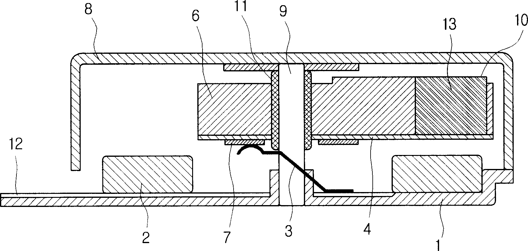
[0001] Related Application Cross Reference [0002] This application claims priority from Korean Patent Application No. 2005-76260 filed with the Korean Intellectual Property Office on Aug. 19, 2005, the disclosure of which is hereby incorporated by reference in its entirety. technical field [0003] The present invention relates to a vibration motor and a brush used in the motor. Background technique [0004] Vibration motors with eccentric rotors are currently widely used in mobile phones, PDAs, etc., as a device that generates vibration when an incoming call is received. As the size of telecommunication equipment decreases, vibration motors are increasingly required to be smaller and thinner. [0005] figure 1 is a cross-sectional view showing the structure of a traditional vibration motor, which has a bracket 1 at the bottom. One end of the shaft 9 is inserted and fixed to the center of the bracket 1 , while the other end of the shaft 9 is fixed by the case 8 . The h...

Claims


Application Information

Patent Timeline
Patent Type & Authority Applications(China)
IPC IPC(8): H01R39/18H01R39/24H02K7/065H02K23/00
CPCH02K5/145H02K7/063H01R39/04H02K1/17H02K13/10
Inventor 寄铉胜
Owner SAMSUNG ELECTRO MECHANICS CO LTD
Learn More