Solar mobile power supply

A technology of mobile power and solar cells, which is applied in the field of power supply and can solve problems such as the lack of mobile power

Inactive Publication Date: 2015-03-18
董彬
View PDF0 Cites 0 Cited by
  • Summary
  • Abstract
  • Description
  • Claims
  • Application Information

AI Technical Summary

Problems solved by technology

[0004] The purpose of the present invention is to provide a solar mobile power supply to solve the problem that the existing mobile power supply does not have banknote detection, function and solar charging function

Method used


Image

  • Solar mobile power supply

Examples


Embodiment 1

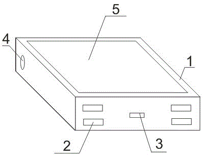
[0011] Such as figure 1 As shown, a solar mobile power supply includes a casing 1, a storage battery, a charging and discharging control circuit, a charging interface and a discharging interface. A hole is opened on the housing 1, and an LED lamp 4 and a condenser cover are arranged in the hole. The LED lamp 4 is an ultraviolet LED, and the ultraviolet LED is connected to a charging and discharging control circuit. There are four discharge interfaces 2, all of which are standard USB interfaces. The surface of the housing 1 is provided with a thin-film solar cell 5 , and the thin-film solar cell 5 is connected to a charging and discharging control circuit.


PUM


Abstract

The invention discloses a solar mobile power supply. The solar mobile power supply comprises a shell, a storage battery, a charge-discharge control circuit, a charge interface and discharge interfaces, wherein a hole is formed in the shell; an LED lamp and a light-condensing cover are arranged in the hole; the LED lamp is an ultraviolet LED; the ultraviolet LED is connected with the charge-discharge control circuit; four discharge interfaces are provided and are all standard USB interfaces; a thin-film solar cell is arranged on the surface of the shell; the thin-film solar cell is connected with the charge-discharge control circuit. According to the solar mobile power supply disclosed by the invention, the ultraviolet LED is designed on the basis of the traditional mobile power supply, thus a money detection function can be provided. Moreover, the design of the four standard USB interfaces is adopted, thus the needs of people can be met. The solar mobile power supply can be charged through the thin-film solar cell, thus the awkwardness of no electricity is avoided.

Description

technical field [0001] The invention belongs to the field of power supplies, and in particular relates to a solar mobile power supply. Background technique [0002] A mobile power supply is a portable charger that integrates power supply and charging functions, and can charge mobile phones and other digital devices anytime, anywhere or standby power. Lithium batteries or dry batteries are generally used as power storage units. The battery that is different from the internal configuration of the product is also called an external battery. It is generally equipped with a variety of power adapters, which usually have the characteristics of large capacity, multi-purpose, small size, long life and safety and reliability. Functional products for power supply or standby charging of various digital products. [0003] Existing mobile power supplies can only charge digital devices, and do not have the function of checking banknotes, which appears to have a single function. Moreover...

Claims


Application Information

Patent Timeline
Patent Type & Authority Applications(China)
IPC IPC(8): H02J7/00
CPCH02J7/0044H02S40/00Y02E10/50
Inventor 董彬
Owner 董彬
Why Eureka
Try Eureka