
Laser radar receiving system

A laser radar and receiving system technology, applied in radio wave measurement systems, instruments, etc., can solve problems such as low receiving efficiency, signal defocus, and insufficient mechanical stability, so as to improve mechanical stability and reliability, reduce Structural redundancy and the effect of reducing errors

Active Publication Date: 2013-07-24
HEFEI INSTITUTES OF PHYSICAL SCIENCE - CHINESE ACAD OF SCI
View PDF5 Cites 27 Cited by
  • Summary
  • Abstract
  • Description
  • Claims
  • Application Information

AI Technical Summary

Problems solved by technology

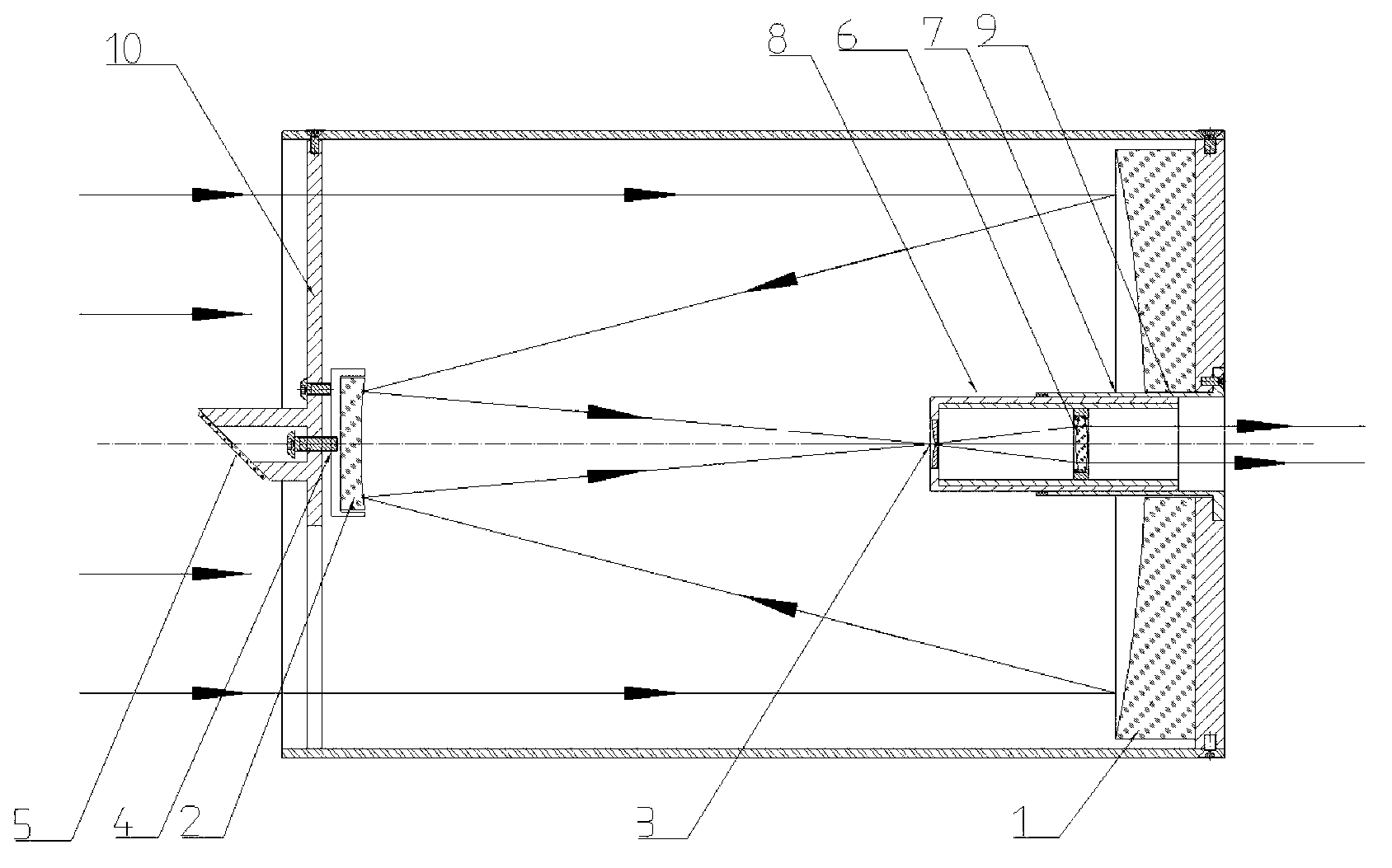
[0006] The technical problem to be solved by the present invention is to provide a novel Cassegrain type telescope, including a telescope unit, a subsequent receiving optical unit, and an adaptive adjustment unit for the field of view, to realize simultaneous detection of laser radar echo signals and detection light of different wavelengths. axis detection and reception, and shape the signal light into quasi-parallel light, and transmit it to the optical telemetry receiving device of the laser radar detection system, so as to solve the problem that the field angle of the receiving telescope cannot be automatically adjusted in the current laser radar optical telemetry receiving system, and the receiving optical system and The detection light of different wavelengths cannot be received coaxially, the signals of different wavelengths are out of focus, the receiving efficiency is low, and the mechanical stability is not enough to meet the needs of the conventional operation of the laser radar system.

Method used


Image

  • Laser radar receiving system

Examples


Embodiment Construction

[0017] Such as figure 1 As shown, the lidar receiving system of the present invention is provided with a Cassegrain telescope, a subsequent receiving optical unit and an adaptive adjustment program for the field of view. The Cassegrain telescope includes a parabolic primary mirror 1 and a hyperboloid secondary mirror 2. The focal plane of the Cassegrain telescope is designed to be located between the parabolic primary mirror 1 and the hyperboloid secondary mirror 2; the laser radar subsequently receives The optical unit is designed and installed inside the telescope barrel, the parabolic primary mirror 1 is provided with a light hole 9, and an aperture diaphragm 3 with adjustable aperture is arranged in the light path of the Cassegrain type telescope. The hyperboloid auxiliary mirror 3 is installed on a four-dimensionally adjustable auxiliary mirror holder 4, and the auxiliary mirror holder 4 is installed in the center of the telescope support cross arm 10, and the support cro...


PUM


Abstract

The invention discloses a laser radar receiving system, which is characterized in that a cassegrain telescope, a subsequent receiving optical unit and a visual field angle adaptive adjusting program are arranged, wherein the focal plane of the cassegrain telescope is positioned between a primary mirror and a secondary mirror; the laser radar subsequent receiving optical unit is arranged in the cassegrain telescope; the aperture of a small-hole diaphragm can be controlled by the visual field angle adaptive adjusting program, so that adaptive adjustment of a visual field angle of the telescope is realized; an output lens seat with a diameter of 52 mm is designed on a supporting cross arm of the telescope; the central line of the lens seat is coaxial with the central axis of the telescope; and the included angle of the normal line of the lens seat and the central axis of the telescope is 45 degrees. The echo signal lights with different detection wavelengths are focused at the center of the small-hole diaphragm through the parabolic primary mirror and the double-curve secondary mirror, and the shaped quasi-parallel signal lights enter the subsequent detection system.

Description

technical field [0001] The invention relates to an optical telemetry receiving device, in particular to an adaptive adjustment program for the subsequent receiving optical unit and field angle of the telescope through the Cassegrain telescope and laser radar. The field angle of the telescope can be adjusted according to the observation conditions and signal quality, etc. Factors are automatically adjusted to achieve coaxial reception of the echo signals of different wavelengths of detection light and the emitted signal light, which has the ability to suppress the light intensity of background signals and improve lidar detection. Background technique [0002] The laser radar receiving system is the key component of the laser radar. Its function is to collect the echo signal light of the detection wavelength emitted by the laser radar, and shape it into quasi-parallel light, and transmit it to the subsequent detection optical system. The quality of its performance directly aff...

Claims


Application Information

Patent Timeline
Patent Type & Authority Applications(China)
IPC IPC(8): G01S7/486G01S7/491
Inventor 董云升陆亦怀刘文清刘建国赵雪松张天舒徐寒杨
Owner HEFEI INSTITUTES OF PHYSICAL SCIENCE - CHINESE ACAD OF SCI
Learn More