
Bait

A technique of fishing bait and fishing line, which is applied to fishing bait. field, can solve problems such as running fish

Inactive Publication Date: 2015-03-25
ZHEJIANG OCEAN UNIV
View PDF5 Cites 5 Cited by
  • Summary
  • Abstract
  • Description
  • Claims
  • Application Information

AI Technical Summary

Problems solved by technology

The existing fishhook and the fish lure part are simply combined together. When the fish bites the fish lure part, the fishhook is only exposed passively. There is a certain time difference. The fish is sensitive and it is easy to let go of the lure within this time difference. In the fish part, there is a phenomenon of running fish

Method used


Image

  • Bait
  • Bait
  • Bait

Examples


Embodiment 1

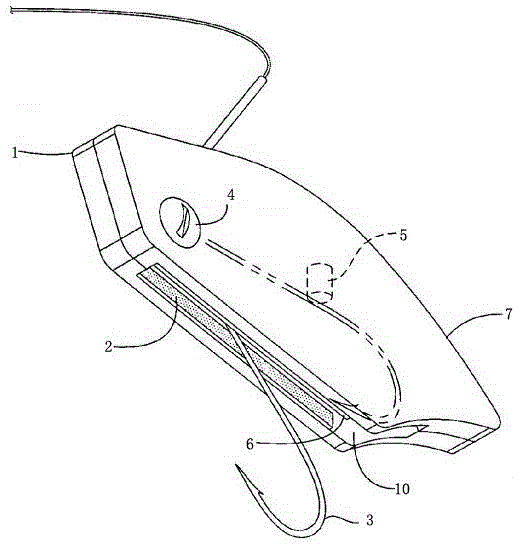
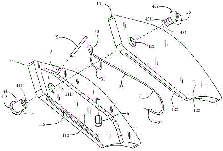
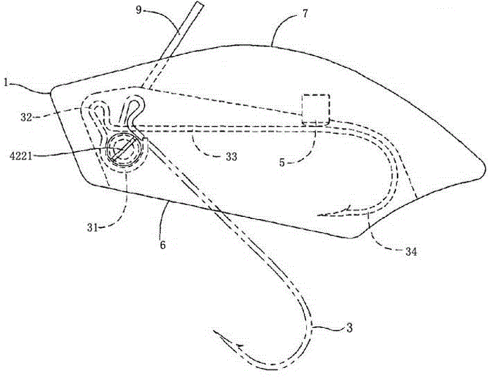
[0023] Example 1, such as figure 1 and 2 As shown, a fishing bait includes a simulated bait body 1, the bait body 1 is composed of an upper light part 7 and a lower heavy part 6, a cavity 2 is arranged inside, and an outlet 10 facing the lower heavy part 6 is provided at one end of the cavity 2. A rotating shaft 4 is arranged in the cavity 2, and the rotating shaft 4 is connected to the inner wall of the cavity 2 in a rotational manner. Fishhook 3 is arranged on rotating shaft 4, and this fishhook 3 is made of collar 31, fishing line ring 32 and barb 34, and barb 34 is arranged towards outlet 10, and connecting rod 33 is set between barb 34 and fishing line ring 32 , the collar 31 is fixedly connected with the rotating shaft 4 . A magnet block 5 is arranged on the inner wall of the cavity 2, and the magnet block 5 is arranged facing the back of the barb 34, and the barb 34 and the magnet block 5 are magnetically connected. A fishing line channel 8 is arranged on the upper l...

Embodiment 2

[0024] Example 2, such as image 3 and 4 The bait shown includes a dummy bait body 1, a cavity 2 is arranged inside, and a rotating shaft 4 is arranged in the cavity 2. The bait body 1 is composed of a left shell 11 and a right shell 12, the left shell 11 and the right shell 12 are arranged symmetrically, and the two are snap-connected. The upper light part 7 is set at the upper end of the left shell 11 and the right shell 12, and the lower heavy part 6 is set at the lower end. A left groove 113 is set on the left shell 11 , a right groove 123 is set on the right shell 12 , and the cavity 2 is composed of the left groove 113 and the right groove 123 . The rotating shaft 4 is rotationally connected with the left groove 113 and the right groove 123 . A left circular hole 111 is provided on the left groove 113 , and a right circular hole 121 is provided on the right groove 123 . The rotating shaft 4 is composed of a left rotating shaft 41 and a right rotating shaft 42, a left...


PUM


Abstract

The invention belongs to the field of fishing equipment, and particularly relates to bait. The bait structurally comprises a simulated bait body and is characterized in that the bait body comprises an upper light portion and a lower heavy portion, a cavity is formed inside, an outlet facing the lower heavy portion is formed in one end of the cavity, a rotating shaft is arranged inside the cavity and is in rotating connection with the inner wall of the cavity, a fishhook is arranged on the rotating shaft, the fishhook is composed of a shaft ring, a fish line ring and a barb, the barb faces the outlet, a connecting rod is arranged between the barb and the fish line ring, the shaft ring is fixedly connected with the rotating shaft, a magnet is arranged on the inner wall of the cavity, the magnet is right opposite to the back of the barb, the barb is in magnetic connection with the magnet, a fish line channel is arranged on the upper light portion, an acute angle is formed between the fish line channel and the connecting rod, and the outlet is matched with the fishhook in size. According to the bait, the fishhook is hidden, the confusion degree is high, the fishhook is used in cooperation with a fish line so that the fish flesh puncture hit rate of the fishhook can be high, and the fish running probability is decreased.

Description

technical field [0001] The invention belongs to the field of fishing equipment, and in particular relates to a fishing bait. Background technique [0002] Bait, that is, food that fish eat. It is the food that lures fish to take the bait when fishing, and it is also an essential thing. According to the principle of fish luring, bait can be divided into real bait and false bait. Whether it is fishing competition or ordinary fishing, bait is always a very important part. Since fake baits are easier to move and use than real baits, most fishermen will choose fake baits. The fake bait usually includes a fish-baiting part and a fishhook. The fishhook is hidden under the fish-baiting part. When the fish bites the fish-baiting part, the inner hook will be exposed to hook the mouth of the fish, and the fish will be fixed on the bait. The existing fishhook and the fish lure part are simply combined together. When the fish bites the fish lure part, the fishhook is only exposed pas...

Claims


Application Information

Patent Timeline
IPC IPC(8): A01K85/02
CPCA01K85/02
Inventor 陈洋慧吕君
Owner ZHEJIANG OCEAN UNIV
Learn More