
Fire identification method

An identification method and fire technology, applied in the field of fire identification, can solve problems such as inability to stop spraying, economic losses to users, malfunction of kitchen fire extinguishing devices, etc., and achieve the effect of preventing false spraying and high accuracy

Inactive Publication Date: 2015-03-25
上海纽特消防设备有限公司
View PDF4 Cites 2 Cited by
  • Summary
  • Abstract
  • Description
  • Claims
  • Application Information

AI Technical Summary

Problems solved by technology

[0002] There are many deficiencies in the existing fire identification methods, especially the fire identification method in the kitchen fire extinguishing device: the control system adopts mechanical linkage, and the mechanical linkage method mainly uses the fusing metal sheet to identify the fire situation. After the fuse is blown, an alarm is sent to the control system and the fire is extinguished. The accuracy of this fire identification method is low, especially under the conditions of the current kitchen fire extinguishing device, and with the cooking method of Chinese chefs, there is a big problem with this fire identification device: the stove Normal open flames in the kitchen will often cause misoperation of the kitchen fire extinguishing device, and the spraying cannot be stopped. Therefore, the false spraying rate of the fire identification method is high, causing very large economic losses to the user

Method used


Image

  • Fire identification method
  • Fire identification method

Examples


Embodiment 1

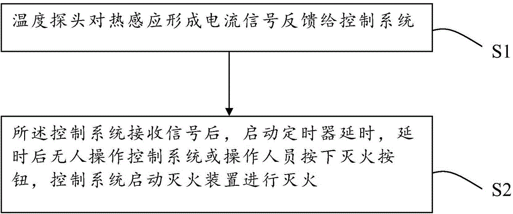
[0023] Embodiment one: a kind of fire identification method, this method comprises the following steps:

[0024] Step S1: The temperature probe 11 forms a current signal for thermal induction and feeds it back to the control system 8;

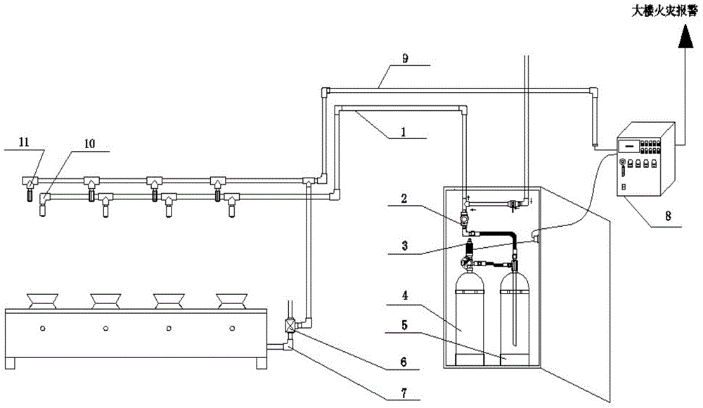
[0025] The temperature probe 11 of the present invention adopts a thermocouple, a thermocouple is a temperature-sensing element, which directly measures the temperature, and converts the temperature signal into a thermoelectromotive force signal, which is converted into the temperature of the measured medium through an instrument. The thermocouple is preferably a platinum thermocouple , installed above the stove; the control system 8 adopts the ATC9852 single-chip industrial control board, the voltage of the input terminal and the output terminal are both DC24V, and the input terminal of the single-chip industrial control board has eight input points. The main input quantities are: temperature detection output signal, start-up Button, stop butt...

Embodiment 2

[0028] Embodiment two: a kind of fire identification method, this method comprises the following steps:

[0029] Step A1: The temperature probe 11 forms a current signal for thermal induction and feeds it back to the control system 8;

[0030] The temperature probe 11 of the present invention adopts a thermocouple, a thermocouple is a temperature-sensing element, which directly measures the temperature, and converts the temperature signal into a thermoelectromotive force signal, which is converted into the temperature of the measured medium through an instrument. The thermocouple is preferably a platinum thermocouple , installed above the stove; the control system 8 adopts the ATC9852 single-chip industrial control board, the voltage of the input terminal and the output terminal are both DC24V, and the input terminal of the single-chip industrial control board has eight input points. The main input quantities are: temperature detection output signal, start-up Button, stop butt...


PUM


Abstract

The invention discloses a fire identification method. The method comprises the following steps: using a temperature probe to form a current signal according to thermo-induction and feed the current signal back to a control system; starting a timer to delay the time after the control system receives the signal, allowing the control system not to be operated by a person after the time is delayed or allowing an operator to press a fire extinguish button; allowing the control system to start a fire extinguishing device to extinguish fire. The fire identification method disclosed by the invention is quite high in accuracy and can be used for effectively preventing the phenomenon of mistaken ejection.

Description

technical field [0001] The invention relates to the technical field of fire protection, in particular to a fire identification method. Background technique [0002] There are many deficiencies in the existing fire identification methods, especially the fire identification method in the kitchen fire extinguishing device: the control system adopts mechanical linkage, and the mechanical linkage method mainly uses the fusing metal sheet to identify the fire situation. After the fuse is blown, an alarm is sent to the control system and the fire is extinguished. The accuracy of this fire identification method is low, especially under the conditions of the current kitchen fire extinguishing device, and with the cooking method of Chinese chefs, there is a big problem with this fire identification device: the stove Normal open flames on the surface often cause misoperation of the kitchen fire extinguishing device, and the spraying cannot be stopped. Therefore, the false spraying rate...

Claims


Application Information

Patent Timeline
IPC IPC(8): A62C37/00
CPCA62C37/04
Inventor 徐凡席
Owner 上海纽特消防设备有限公司
Learn More