WVR (wave vapor recompression) continuous vaporization system
A technology of vapor recompression and evaporation system, applied in the direction of multi-effect evaporation, evaporator accessories, etc., to achieve high efficiency, excellent operating performance with liquid, and small structure size.
- Summary
- Abstract
- Description
- Claims
- Application Information
AI Technical Summary
Problems solved by technology
Method used
Image
Examples
Embodiment 1
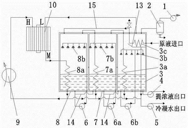
[0018] Example 1 The recompression of the secondary steam is completed in the phase change gas wave supercharger by using the driving steam.
[0019] figure 1 A gas wave vapor recompression continuous evaporation system is shown. In the figure, the gas wave vapor recompression continuous evaporation system includes a three-effect evaporator, concentrated liquid pump 4, condensate water pump 5, steam boiler 9, phase change gas wave supercharger 10 and vacuum pump 1. The three-effect evaporator consists of the first effect An evaporator 8, a secondary effect evaporator 7 and a final effect evaporator 3 are formed, and the bottoms of the first effect evaporator 8 and the secondary effect evaporator 7, and the bottoms of the secondary effect evaporator 7 and the final effect evaporator 3 are connected to each other by a communication pipe 14. The first effect circulation pump 6 of the first effect evaporator 8 is used to connect the first effect liquid uniform distributor 8b...
Embodiment 2
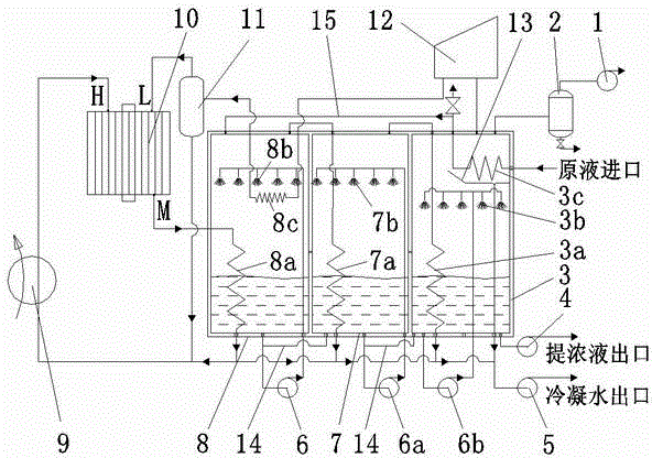
[0024] Example 2 Combined use of steam compressor and phase change gas wave supercharger to complete the recompression of secondary steam.
[0025] figure 2 A continuous evaporation system combining mechanical vapor compression with gas wave vapor recompression is shown. figure 2 and figure 1 The difference is that: the upper space of the final effect evaporator 3 is connected to the phase-change gas wave supercharger 10 through the steam compressor 12, the heat exchanger 8c located in the upper space of the first effect evaporator 8, and the gas-liquid separator 11 in sequence. The low-pressure steam inlet L, the bottom of the gas-liquid separator 11 is connected to the steam boiler 9 and the water inlet of the condensate pump 5 .
[0026] In each effect evaporator, the heat exchange on the evaporating side adopts a forced circulation liquid distributor to complete the liquid distribution. In the co-current and co-current feeding methods, the feed liquid of the front eff...
PUM
 Abstract
Description
Claims
Application Information
 - R&D
- Intellectual Property
- Life Sciences
- Materials
- Tech Scout
- Unparalleled Data Quality
- Higher Quality Content
- 60% Fewer Hallucinations
Browse by: Latest US Patents, China's latest patents, Technical Efficacy Thesaurus, Application Domain, Technology Topic, Popular Technical Reports.
© 2025 PatSnap. All rights reserved.Legal|Privacy policy|Modern Slavery Act Transparency Statement|Sitemap|About US| Contact US: help@patsnap.com


