A gas wave vapor recompression continuous evaporation system

A technology of vapor recompression and evaporation system, applied in the direction of multi-effect evaporation, evaporator accessories, etc., to achieve the effect of low speed, easy development, and excellent liquid operation performance

Active Publication Date: 2016-03-02
DALIAN UNIV OF TECH
View PDF6 Cites 0 Cited by
  • Summary
  • Abstract
  • Description
  • Claims
  • Application Information

AI Technical Summary

Problems solved by technology

The CN101290174 patent provides a principle structure of an outer circulation dissipative air wave machine. Such an open air wave rotor structure at both ends can complete the energy exchange of high and low pressure fluids, but at present only its expansion effect is used

Method used


Image

  • A gas wave vapor recompression continuous evaporation system
  • A gas wave vapor recompression continuous evaporation system

Examples


Embodiment 1

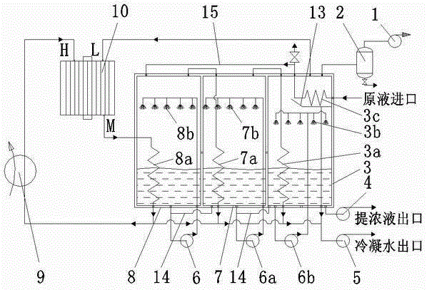
[0018] Example 1 The recompression of the secondary steam is completed in the phase change gas wave supercharger by using the driving steam.

[0019] figure 1 A gas wave vapor recompression continuous evaporation system is shown. In the figure, the gas wave vapor recompression continuous evaporation system includes a three-effect evaporator, concentrated liquid pump 4, condensate water pump 5, steam boiler 9, phase change gas wave supercharger 10 and vacuum pump 1. The three-effect evaporator consists of the first effect An evaporator 8, a secondary effect evaporator 7 and a final effect evaporator 3 are formed, and the bottoms of the first effect evaporator 8 and the secondary effect evaporator 7, and the bottoms of the secondary effect evaporator 7 and the final effect evaporator 3 are connected to each other by a communication pipe 14. The first effect circulation pump 6 of the first effect evaporator 8 is used to connect the first effect liquid uniform distributor 8b in...

Embodiment 2

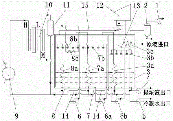
[0024] Example 2 Combined use of steam compressor and phase change gas wave supercharger to complete the recompression of secondary steam.

[0025] figure 2 A continuous evaporation system combining mechanical vapor compression with gas wave vapor recompression is shown. figure 2 and figure 1 The difference is that the upper space of the final effect evaporator 3 is connected to the phase-change gas wave supercharger through the steam compressor 12, the cooling heat exchanger 8c located in the upper space of the first effect evaporator 8, and the gas-liquid separator 11 in sequence. The low-pressure steam inlet L of 10, the bottom of the gas-liquid separator 11 is connected to the water inlet of the steam boiler 9 and the condensate pump 5.

[0026] In each effect evaporator, the heat exchange on the evaporating side adopts a forced circulation liquid distributor to complete the liquid distribution. In the co-current and co-current feeding methods, the feed liquid of the ...


PUM


Abstract

A gas wave vapor recompression continuous evaporation system belongs to the technical field of thermal evaporation. The core is to introduce a phase-change gas wave supercharger, and use the characteristics of shock wave heating and supercharging to complete gas wave steam recompression, and realize two systems of gas wave steam recompression and gas wave supercharging / mechanical compression, and the final effect is secondary The steam enters the phase-change gas wave supercharger to complete recompression, and after the energy taste is improved, it enters the first-effect evaporator as a driving heat source, and the generated secondary steam continues to evaporate as a lower-effect heat source after the gas-liquid separation module is separated; After each effect evaporator is concentrated to a saturated concentration, it is pumped out of the device. The system of the invention is simple, not only overcomes the design and manufacturing difficulties of the steam compressor, but also has the advantage of higher pressurization efficiency than the steam ejector.

Description

technical field [0001] The invention relates to a gas wave vapor recompression continuous evaporation system, which belongs to the technical field of thermal evaporation. Background technique [0002] The arbitrary discharge of high-salt wastewater with a salinity greater than 1% has brought enormous pressure to the ecological environment, which has attracted widespread attention from the government and the public, and there is an urgent need for cost-effective high-salt wastewater treatment technology. Among the three mainstream desalination technologies today, the reverse osmosis membrane (RO) method is economical, but has problems such as membrane fouling and low production capacity; The energy consumption of the method is high (for example, the three-effect MED consumes about 0.4 tons of fresh steam / ton of wastewater), and the economy is poor. The industry even believes that the thermal method is not the development direction of the brine treatment technology. However, ...

Claims


Application Information

Patent Timeline
Patent Type & Authority Patents(China)
IPC IPC(8): B01D1/26B01D1/30
Inventor 代玉强胡大鹏刘凤霞程永航朱彻邹久朋张斯亮陶盛洋
Owner DALIAN UNIV OF TECH
Why Eureka
Try Eureka