Hot liquid injection multi-unit vapor compression device and heat pump

A vapor compression and multi-unit technology, applied in the field of compressors and heat pumps, can solve problems such as temperature rise, environmental pollution, and limited use range, and achieve the effect of high boost ratio and low energy consumption

Active Publication Date: 2021-08-17
傅朝清
View PDF28 Cites 0 Cited by
  • Summary
  • Abstract
  • Description
  • Claims
  • Application Information

AI Technical Summary

Problems solved by technology

The bigger problem is that the steam needed in the process is generated by burning or consuming energy, such as coal, oil, etc., which are produced by boilers. The burning of energy not only produces carbon dioxide emissions (that is, carbon emissions) and harmful gas emissions, but also Waste residue, waste liquid, etc. are discharged; the secondary steam condensation has to use a large amount of circulating water, and the circulating water discharges its heat to the atmosphere through the circulating water cooling tower by means of water evaporation or heating air, resulting in a large amount of waste heat discharge into the atmosphere, pollute the environment, and raise the temperature
With the same pressure energy and small nozzle, the flow rate is relatively small. The degree of dispersion of the superheated condensate sprayed after the nozzle is high, and the efficiency of compressing the secondary steam is high. On the contrary, as the nozzle diameter increases, the flow rate also increases correspondingly, and the superheated condensate behind the nozzle The degree of dispersion will drop sharply, and the efficiency of compressing the secondary steam will also drop sharply. That is to say, the use of the existing jet suction device to compress the secondary steam has limited utilization capacity and more limited application range.

Method used


Image

  • Hot liquid injection multi-unit vapor compression device and heat pump
  • Hot liquid injection multi-unit vapor compression device and heat pump
  • Hot liquid injection multi-unit vapor compression device and heat pump

Examples


Embodiment 1

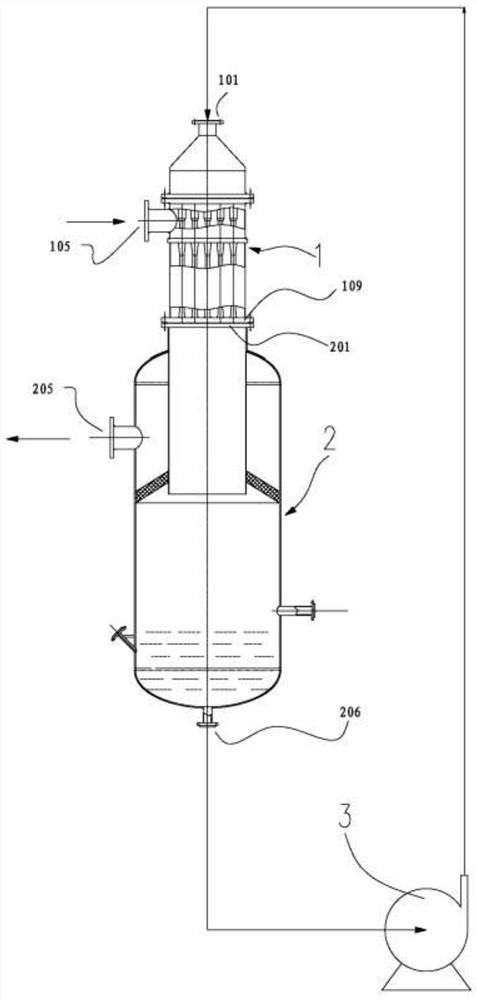
[0116] Such as figure 1 As shown, the present invention provides a thermal liquid injection multi-unit vapor compression device, the thermal liquid injection multi-unit vapor compression device comprises a thermal liquid injection multi-unit vapor compressor 1, a secondary expansion separation chamber 2, a thermal liquid cycle The booster pump 3; the hot liquid injection multi-unit vapor compressor 1 has a booster cycle hot liquid inlet 101, a low-grade steam or secondary steam inlet 105, and a flower plate 109 at the outlet of the multi-compression unit; the two-stage expansion separation Chamber 2 has an inlet 201 for two-phase flow, a hot liquid outlet 206, and a pressurized saturated vapor outlet 205;

[0117] The supercharged hot liquid outlet of the hot liquid circulation booster pump 3 communicates with the hot liquid inlet 101 of the hot liquid injection multi-unit vapor compressor 1; the low-grade steam or secondary The steam inlet 105 communicates with the low-grade...

Embodiment 2

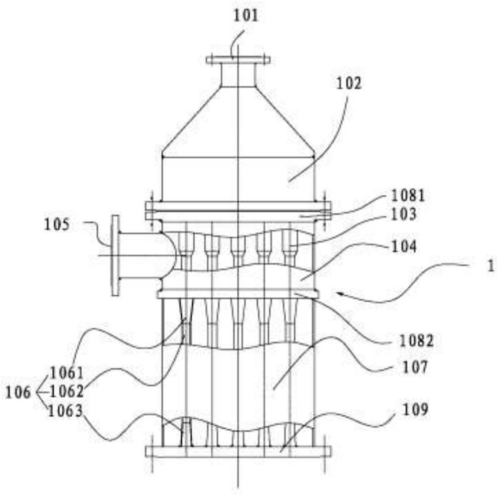
[0123] Such as figure 2 As shown, the thermal liquid injection multi-unit vapor compression device includes a thermal liquid injection multi-unit vapor compressor 1, a secondary expansion separation chamber 2, and a hydrothermal circulation booster pump 3; the thermal liquid injection multi-unit vapor compressor 1. It includes a liquid chamber 102 with a conical head or an elliptical head and a cylindrical inner cavity, a gas-liquid mixing chamber 104 with a cylindrical inner cavity, an upper flower plate 1081, and a lower flower plate 1082, and a cylindrical inner cavity And the multi-compression unit chamber 107 with the flower plate 109 of the multi-compression unit outlet at the bottom;

[0124] The conical head or oval head of the liquid chamber 102 is provided with a pressurized circulation hot liquid inlet 101; the upper flower plate 1081 of the gas-liquid mixing chamber 104 is equipped with a plurality of nozzles 103, and the number of nozzles 103 is ≥ 2 And communic...

Embodiment 3

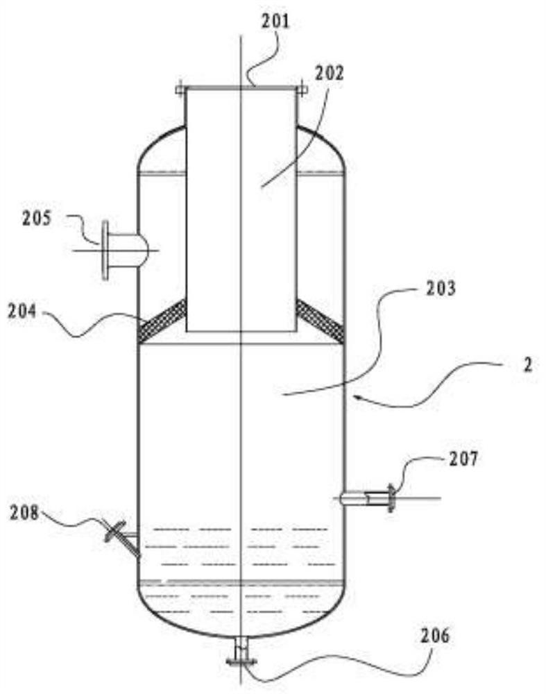
[0130] Such as image 3 As shown, the thermal liquid injection multi-unit vapor compression device includes a thermal liquid injection multi-unit vapor compressor 1, a secondary expansion separation chamber 2, and a hydrothermal circulation booster pump 3; the secondary expansion separation chamber 2 includes A first-stage expansion separation chamber 202 with a cylindrical inner cavity, a second-stage expansion separation chamber 203 with an upper oval head or a butterfly head, a lower oval head or a butterfly head, and a cylindrical inner cavity, There is an umbrella-shaped wire mesh demister 204 between the inner wall of the cylindrical inner cavity of the second-stage expansion separation chamber 203 and the outer wall of the cylindrical inner cavity of the first-stage expansion separation chamber 202;

[0131] The upper end of the first stage expansion separation chamber 202 has a two-phase flow inlet 201, and the lower end has the outlet of the first stage expansion sepa...


PUM


Abstract

The invention discloses an efficient hot liquid injection multi-unit vapor compression device and heat pump, and belongs to the field of compressors and heat pumps. According to the hot liquid injection multi-unit vapor compression device, pressurized saturated steam condensate, namely hot liquid, is used for compressing low-grade steam or secondary steam with the same component, due to the fact that the temperature of the hot liquid is high, condensation of the low-grade steam or the secondary steam is not generated, the low-grade steam or the secondary steam is compressed in high-speed two-phase flow, the whole compression process is carried out under the condition that a large amount of hot liquid exists. More than 80% of energy is consumed to increase temperature and be overheated, and less than 20% of energy is used for pressurization when thermal insulation compression is carried out as an MVR, all mechanical compressors and a vapor injection heat pump; the energy consumption is low and the supercharge ratio is high; a heat pump formed by the heat pump, an evaporator, a rectifying tower and the like can complete target production capacity without generating steam and cooling water by a boiler, so that the purposes of greenness, low carbon, carbon reduction and efficiency improvement are achieved; in addition, the second-stage expansion separation chamber is used as a second-stage expansion evaporation chamber of the evaporator and has the characteristics of high evaporation efficiency and good gas-liquid separation; the application field is very wide.

Description

technical field [0001] The invention relates to the fields of compressors and heat pumps, in particular to a thermal liquid injection multi-unit vapor compression device and a heat pump. Background technique [0002] As we all know: the utilization of low-grade steam or secondary steam is a major issue in today's energy saving and emission reduction, green low-carbon economy, carbon neutrality and circular economy. [0003] In the prior art, the following methods are generally adopted to realize the energy-saving utilization of low-grade steam or secondary steam. [0004] 1. Mechanical vapor recompression technology, referred to as MVR (mechanical vapor recompression) [0005] MVR is an energy-saving technology that re-uses the energy of the secondary steam generated by evaporation to reduce the demand for external energy. Its working process is to compress the secondary steam through the MVR compressor, increase the temperature and pressure, and increase the enthalpy, and ...

Claims


Application Information

Patent Timeline
Patent Type & Authority Applications(China)
IPC IPC(8): F04F5/16F04F5/18F04F5/36F04F5/46F25B30/02
CPCF04F5/16F04F5/36F04F5/46F04F5/18F25B30/02
Inventor 傅朝清李赛傅皓
Owner 傅朝清
Why Eureka
Try Eureka