Novel small-size duct turbofan engine

A turbofan engine, turbojet engine technology, applied in the direction of machine/engine, jet propulsion device, etc., can solve the problems of high technical difficulty and increased cost, and achieve the effects of low fuel consumption, simple structure and small volume

Inactive Publication Date: 2013-07-24
李宇霞
View PDF4 Cites 9 Cited by
  • Summary
  • Abstract
  • Description
  • Claims
  • Application Information

AI Technical Summary

Problems solved by technology

[0010] However, due to the small size and light weight of the small turbofan engine, the technical difficulty required to develop a small turbofan engine with traditional technology is extremely difficult, and the cost will also increase significantly. It is necessary to seek a new design concept and technical means to develop small turbofan engines

Method used


Image

  • Novel small-size duct turbofan engine
  • Novel small-size duct turbofan engine
  • Novel small-size duct turbofan engine

Examples


Embodiment 1)

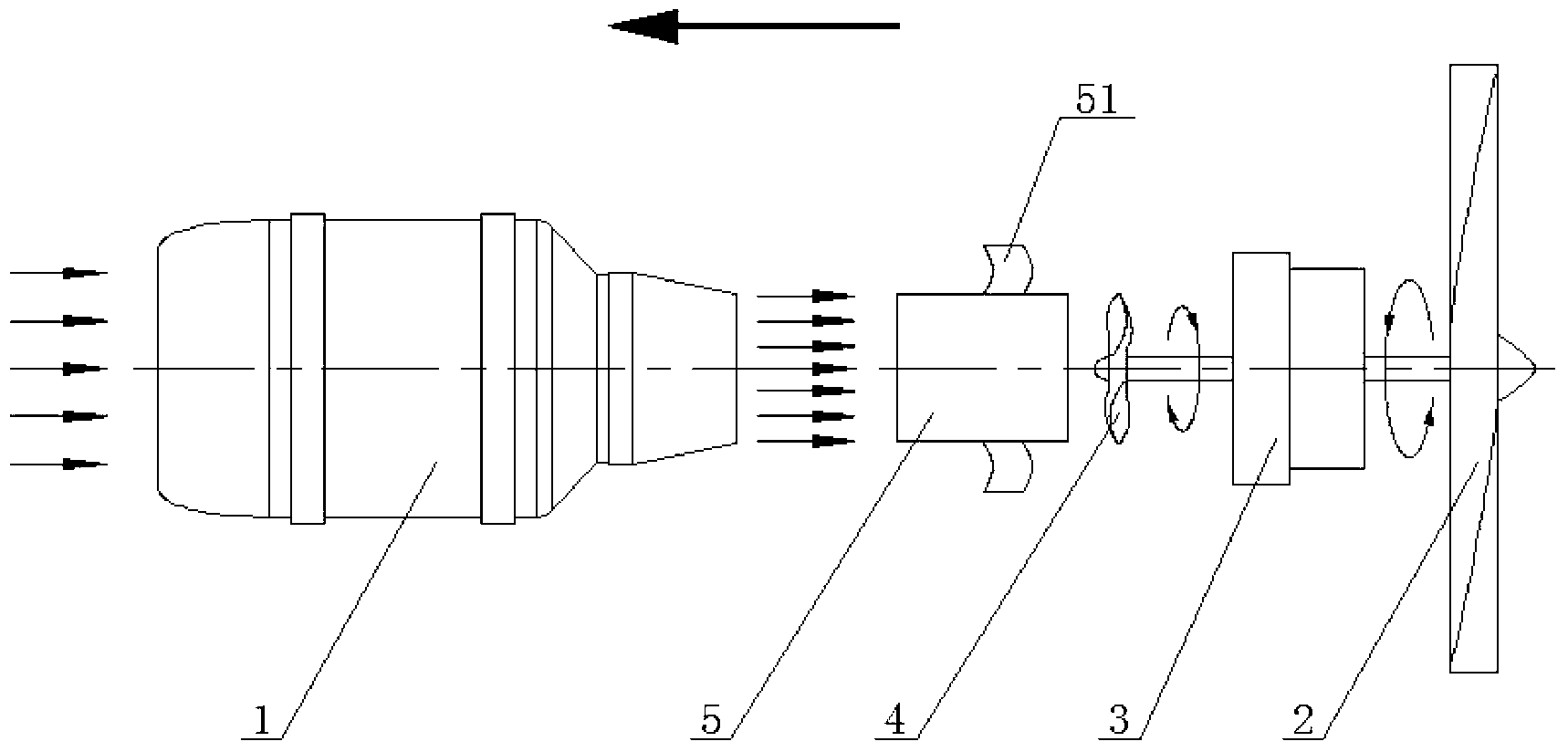
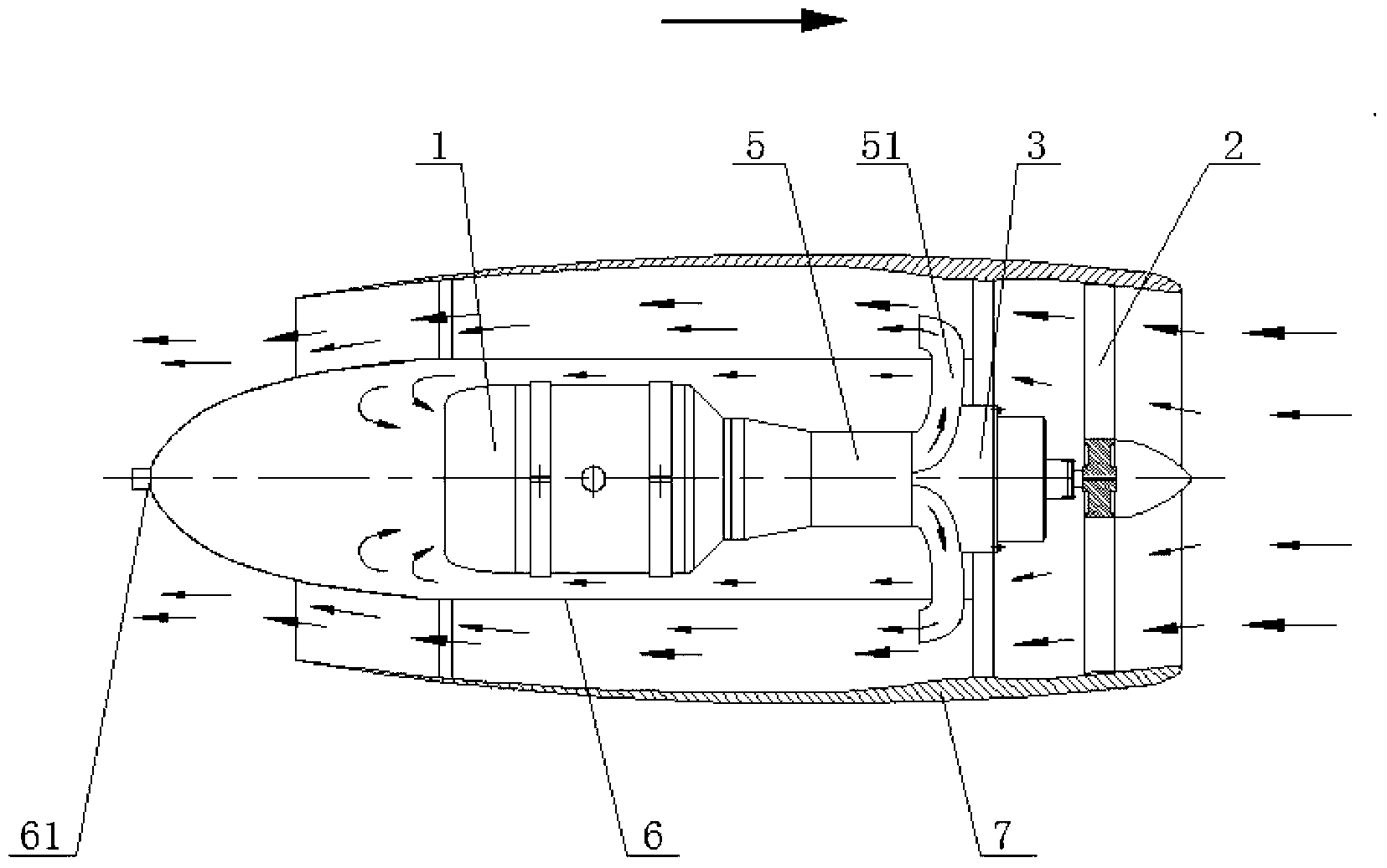
[0024] See figure 1 and figure 2 , the present invention has a turbojet engine 1 and a thrust fan 2; the thrust fan 2 is fixedly connected to the shaft at one end of the speed reducer 3, and a free turbine 4 is fixedly connected to the shaft at the other end of the speed reducer 3; the outer casing of the free turbine 4 A section of housing 5 is provided; one end of the housing 5 is airtightly connected with the airflow injection port of the turbojet engine 1, and the other end is airtightly connected with the end of the speed reducer 3 near the free turbine 4; the free turbine 4 The diameter is less than the diameter of the thrust fan 2; the outside of the turbojet engine 1 is provided with an engine intake guide cover 6, and the guide end of the engine intake guide cover 6 is provided with an engine intake air flow regulating hole 61; The air guiding cover 6, the speed reducer 3 and the thrust fan 2 are provided with an outer duct 7; the end of the casing 5 connected to th...

Embodiment 2)

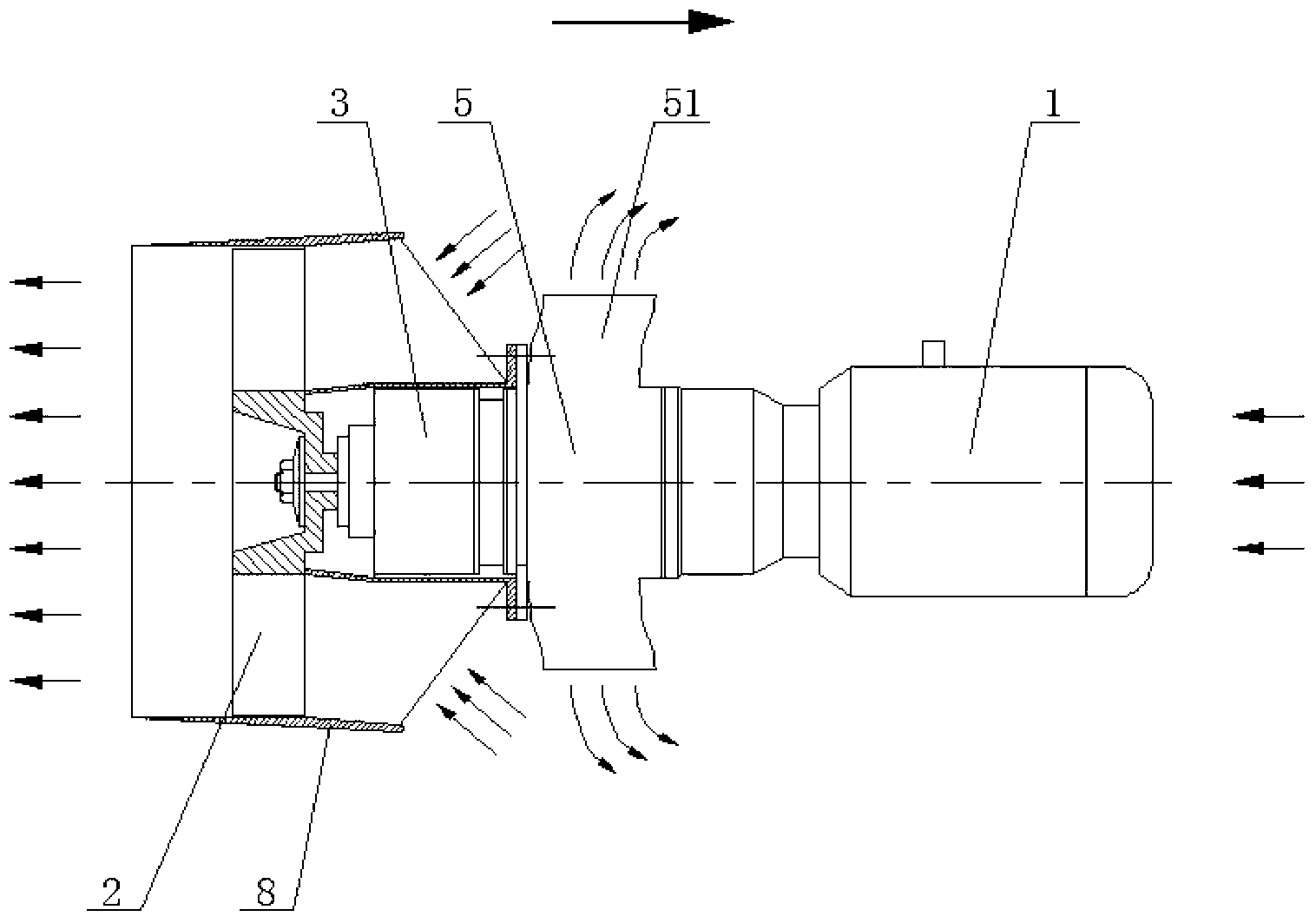
[0026] See figure 1 and image 3 , the present invention has a turbojet engine 1 and a thrust fan 2; the thrust fan 2 is fixedly connected to the shaft at one end of the speed reducer 3, and a free turbine 4 is fixedly connected to the shaft at the other end of the speed reducer 3; the outer casing of the free turbine 4 A section of housing 5 is provided; one end of the housing 5 is airtightly connected with the airflow injection port of the turbojet engine 1, and the other end is airtightly connected with the end of the speed reducer 3 near the free turbine 4; the free turbine 4 The diameter is smaller than that of the thrust fan 2; the reducer 3 and the thrust fan 2 are provided with a fan casing 8; the side of the casing 5 is evenly distributed with exhaust pipes 51.

[0027] Embodiment 1 and embodiment 2 all are to directly blow the free turbine 4 by the high-speed tail jet flow of the turbojet engine 1, so that the free turbine 4 rotates at a high speed, and the high-spe...


PUM


Abstract

The invention relates to a novel small-size duct turbofan engine. The novel small-size duct turbofan engine is provided with a turbojet engine and a thrust fan, wherein the thrust fan is fixedly connected with a shaft at one end of a speed reducer, a free turbine is fixedly connected on a shaft at the other end of the speed reducer, a section of shell is sleeved outside the free turbine, one end of the shell is in communication connection with the end, with an airflow injection mouth, of the turbojet engine in a sealed mode, the other end of the shell is connected with the end, close to the free turbine, of the speed reducer in a sealed mode, an exhaust pipe is arranged on the shell, and the diameter of the free turbine is smaller that that of the thrust fan. The novel small-size duct turbofan engine is improved based on an existing turbofan engine and has the advantages that the structure is simple, assistance is provided for the miniaturization of the turbofan engine, fuel consumption is low, and thrust can be multiplied by unit oil consumption. Compared with a small-size turbojet engine used for a fuel gas generator, the novel small-size duct turbofan engine has the advantages that the thrust generated by the novel small-size duct turbofan engine can be about four times of the thrust of the turbojet engine of the built-in fuel gas generator.

Description

technical field [0001] The invention relates to a propulsion engine, in particular to a novel small ducted turbofan engine. Background technique [0002] Throughout the development history of modern aircraft power plants, the emergence of aviation gas turbojet engines (hereinafter referred to as turbojet engines) has finally led to earth-shaking changes in aircraft performance, which is of epoch-making significance. Gas turboprop engine (referred to as turboprop engine), gas turbofan engine (referred to as turbofan engine) and gas turboshaft engine (referred to as turboshaft engine) were born. As the technology matures, it is gradually applied to the aviation field In various departments, large-scale aeroengines with high thrust have been widely used in civil aircraft and military transport aircraft. [0003] The working principle of turbojet engine and turbofan engine is as follows: [0004] 1) The turbojet engine is a direct reaction propulsion device [0005] When the ...

Claims


Application Information

Patent Timeline
Patent Type & Authority Applications(China)
IPC IPC(8): F02K3/00
Inventor 李宇霞
Owner 李宇霞
Why Eureka
Try Eureka