Jet engine

A jet engine and compressor technology, applied in the direction of machines/engines, jet propulsion devices, gas turbine devices, etc., can solve the problems of complex engine structure and control system, reduced structure and strength reliability, and reduced aerodynamic stability, etc., to achieve Simplified engine structure, widened working range, and reduced weight

Inactive Publication Date: 2010-02-17
刘佳骏
View PDF0 Cites 24 Cited by
  • Summary
  • Abstract
  • Description
  • Claims
  • Application Information

AI Technical Summary

Problems solved by technology

A high boost ratio requires more stages of compressors to be realized, which will lead to lengthening of the connecting shaft between the compressor and the turbine, and high gas temperature requires high-performance high-temperature-resistant materials, which makes the structure of the engine complex and technically difficult , increased processing costs, reduced structure and strength reliability
In addition, since the output power of the turbine is restricted by factors such as the flow rate of the compressor, the boost ratio, the outlet temperature of the combustion chamber, and the rotational speed of the rotating shaft, there is a problem of matching the work of the compressor and the turbine.
The high boost ratio and many stages lead to the decrease of the aerodynamic stability of the compressor at low speed, and unstable working states such as rotating stall and surge
In order to alleviate the stability problem of the compressor at low speed, the turbojet engine often needs to adopt measures such as multi-stage compressor intermediate stage discharge, multi-rotor (double rotor or three rotor), adjustable inlet guide vanes and stator blades, etc. Prevent compressor surge, make the structure and control system of the engine more complicated

Method used


Image

  • Jet engine
  • Jet engine
  • Jet engine

Examples


Embodiment 1

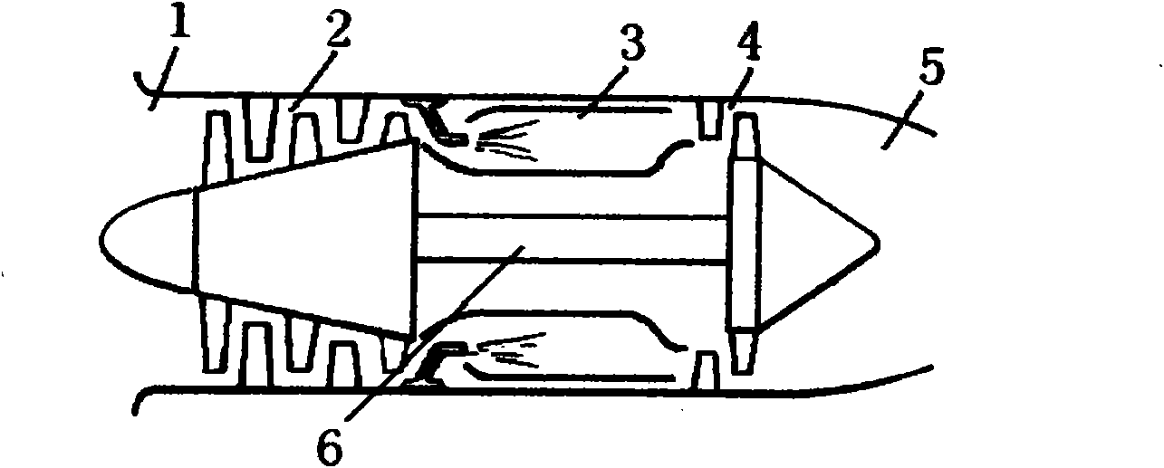
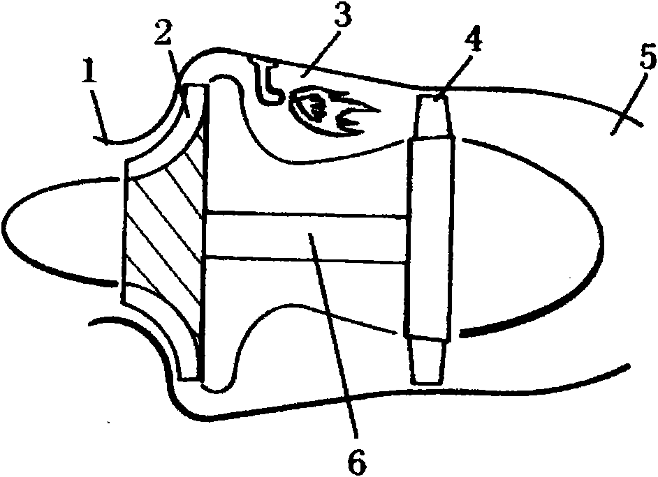
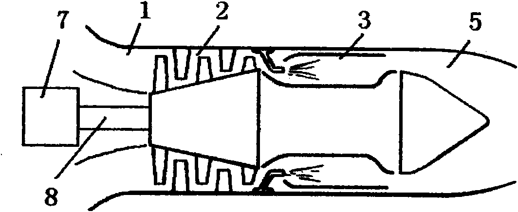
[0022] The jet engine of the present embodiment is made up of inlet duct (1), compressor (2), combustion chamber (3), tail nozzle (5) and independent power unit (7), and independent power unit (7) is a A gas turbine device is installed on the inlet side of the compressor (2), and its power output shaft (8) is connected with the compressor (2), and the compressor (2) adopts an axial flow compressor.

Embodiment 2

[0024] The jet engine of the present embodiment is made up of intake passage (1), air compressor (2), combustion chamber (3), tail pipe (5) and independent power unit (7), and independent power unit (7) is triangular The rotary engine is installed on the outlet side of the compressor (2), and its power output shaft (8) is connected with the compressor (2), and the compressor (2) adopts an axial flow compressor.

Embodiment 3

[0026] The jet engine of the present embodiment is made up of intake passage (1), air compressor (2), combustion chamber (3), tail nozzle (5) and independent power unit (7), and independent power unit (7) is reciprocating The piston engine is installed on the inlet side of the air compressor (2), and its power output shaft (8) is connected with the air compressor (2), and the air compressor (2) adopts a radial flow air compressor.


PUM


Abstract

The invention provides a jet engine, which is mainly characterized by consisting of an air inlet (1), a gas compressor (2), a combustion chamber (3), a tail nozzle (5) and an independent power plant (7), wherein a power output shaft (8) of the independent power plant (7) is connected with the compressor (2) and drives the gas compressor (2) to rotate to work. By adopting the independent power plant capable of independently changing the output power to replace a turbine in the prior art, the jet engine effectively reduces the pressure ratio of the gas compressor under the condition of same thrust, and avoids the problem of poor aerodynamic stability caused by the matched work of the gas compressor and the turbine; and the engine can better work under different loads, thereby simplifying a structure of the engine, avoiding the surge phenomenon of the gas compressor, and increasing the work scope and the reliability.

Description

(1) Technical field: [0001] The invention relates to the field of aeroengines, especially jet engines. (two) background technology: [0002] The jet engine that the continuous jet that aviation vehicle adopts produces thrust is mainly turbojet engine, and turbofan engine is similar to turbojet engine, all is to generate thrust by high-speed exhaust, but the structure is more complicated. The turbojet engine has the characteristics of small size, light weight, and high thrust. However, the exhaust velocity at the outlet of its tail nozzle is high. When the aircraft is flying at low speed, the propulsion efficiency of the engine is low and the fuel consumption rate is high. The exhaust velocity of a turbofan engine is less than that of a turbojet engine, and its propulsion efficiency is higher than that of a turbojet engine when flying at a low speed, but the propulsion efficiency will decline when flying at a high speed. [0003] The turbojet engine of prior art is made up o...

Claims


Application Information

Patent Timeline
Patent Type & Authority Applications(China)
IPC IPC(8): F02C3/00F02K3/00
Inventor 刘佳骏
Owner 刘佳骏
Why Eureka
Try Eureka