External thread turning fixture of thin-wall sleeve

A technology of thread turning and thin-wall sleeves, which is applied in the field of mechanical processing, can solve problems affecting dimensional accuracy and shape tolerance, weak strength, vibration deformation, etc., and achieve the effect of simple and compact structure, convenient mass production, and high processing accuracy

Inactive Publication Date: 2015-03-25
XIAN ZHIYUE ELECTROMECHANICAL TECH
View PDF0 Cites 14 Cited by
  • Summary
  • Abstract
  • Description
  • Claims
  • Application Information

AI Technical Summary

Problems solved by technology

[0002] Due to the characteristics of thin wall, poor rigidity and weak strength, the thin-walled sleeve is prone to stress deformation, heat deformation and vibration deformation during its processing.
When turning the external thread of the thin-walled sleeve, it needs to be clamped by the three-jaw chuck on the spindle of the lathe. However, due to the thin wall, poor rigidity and weak strength of the thin-walled sleeve, under the action of the clamping force of the three-jaw chuck It is very easy to deform, which affects the precision requirements of its dimensional accuracy and shape tolerance. At the same time, because the thin-walled sleeve is thin, the cutting heat generated during the turning process will cause thermal deformation of the thin-walled sleeve, making the thin-walled sleeve The size of the sleeve is more difficult to guarantee and control

Method used


Image

  • External thread turning fixture of thin-wall sleeve
  • External thread turning fixture of thin-wall sleeve
  • External thread turning fixture of thin-wall sleeve

Examples


Embodiment Construction

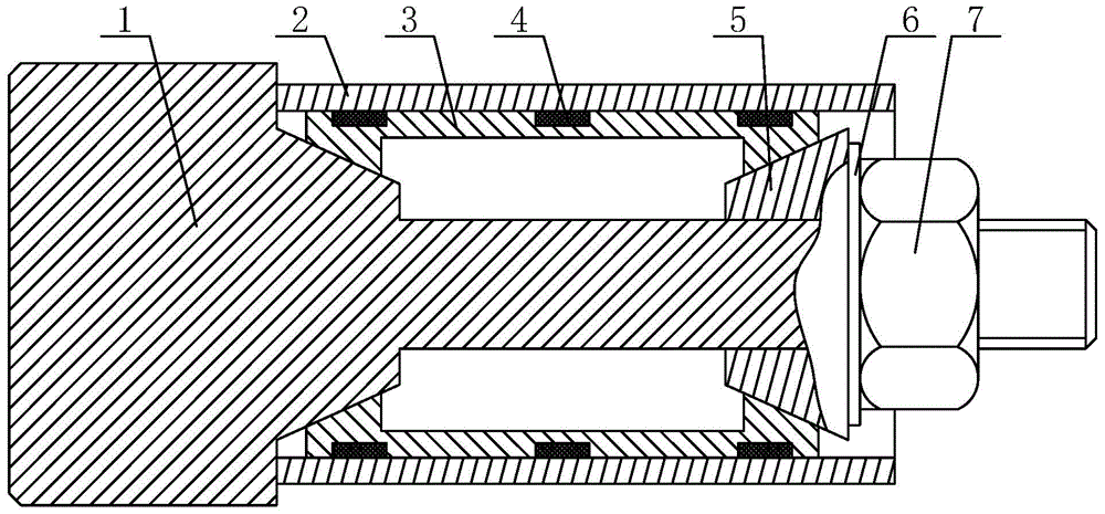
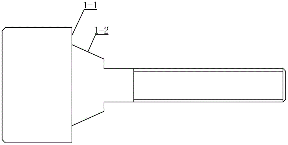
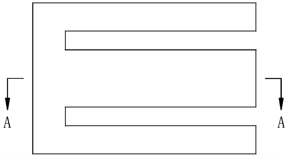
[0022] Such as Figure 1-Figure 4 A thin-walled sleeve external thread turning fixture shown includes a stepped threaded shaft 1, an elastic expansion sleeve 3 and a taper sleeve 5; one end of the stepped threaded shaft 1 is provided with a positioning table 1 for positioning the workpiece 2 to be processed -1, on the side of the positioning platform 1-1, the stepped threaded shaft 1 is provided with an outer tapered surface 1-2 having the same taper as the taper sleeve 5, and the stepped threaded shaft 1 is set with a The elastic expansion sleeve 3 that pushes against and supports the workpiece 2 to be processed is provided with a taper sleeve 5 between the elastic expansion sleeve 3 and the stepped threaded shaft 1, and the inner sides of both ends of the elastic expansion sleeve 3 are provided with The inner tapered surface 3-1 having the same taper as the taper sleeve 5, the outer side of the elastic expansion sleeve 3 is provided with a plurality of mounting grooves 3-2 f...


PUM


Abstract

The invention discloses an external thread turning fixture of a thin-wall sleeve. The fixture comprises a step thread shaft, an elastic expansion sleeve and a taper sleeve, wherein a positioning table is arranged at one end of the step thread shaft; an outer conical surface is arranged on the step thread shaft at one side of the positioning table; the step thread shaft is coated by the elastic expansion sleeve; the taper sleeve is arranged between the elastic expansion sleeve and the step thread shaft; inner conical surfaces having the same taper with the taper sleeve are respectively arranged at the inner sides of the two ends of the elastic expansion sleeve; multiple rubber strips for increasing the frictional force between the elastic expansion sleeve and a workpiece to be machined are arranged at the outer side of the elastic expansion sleeve through mounting grooves; and a pressing nut for tightly pressing the taper sleeve is arranged on the step thread shaft. The fixture has the characteristics of reasonable design, simple structure, high machining precision, convenience for workpiece disassembly, low labor intensity, high production efficiency, long service life, low production cost and convenience for promotion and application.

Description

technical field [0001] The invention belongs to the technical field of mechanical processing, and relates to a turning clamp, in particular to a clamp for turning the external thread of a thin-walled sleeve. Background technique [0002] Due to the characteristics of thin wall, poor rigidity and weak strength, the thin-walled sleeve is prone to stress deformation, thermal deformation and vibration deformation during its processing. When turning the external thread of the thin-walled sleeve, it needs to be clamped by the three-jaw chuck on the spindle of the lathe. However, due to the thin wall, poor rigidity and weak strength of the thin-walled sleeve, under the action of the clamping force of the three-jaw chuck It is very easy to deform, which affects the precision requirements of its dimensional accuracy and shape tolerance. At the same time, because the thin-walled sleeve is thin, the cutting heat generated during the turning process will cause thermal deformation of the...

Claims


Application Information

Patent Timeline
Patent Type & Authority Applications(China)
IPC IPC(8): B23B31/40
CPCB23B31/404
Inventor 黄冰
Owner XIAN ZHIYUE ELECTROMECHANICAL TECH
Why Eureka
Try Eureka