Automatic drilling frame for instrument panel beam drilling device

A drilling device and instrument panel technology, which is applied in the direction of drilling/drilling equipment, boring/drilling, boring machine/drilling machine parts, etc., can solve the problem that drilling cannot be carried out quickly and stably, and achieve improved drilling Pore ​​efficiency, simple structure, and convenient use

Inactive Publication Date: 2015-03-25
CHONGQING HUAQING AUTOMOBILE PARTS
View PDF12 Cites 12 Cited by
  • Summary
  • Abstract
  • Description
  • Claims
  • Application Information

AI Technical Summary

Problems solved by technology

However, there is no drilling frame suitable for the device at present, so that the drilling still cannot be carried out quickly and stably.

Method used


Image

  • Automatic drilling frame for instrument panel beam drilling device
  • Automatic drilling frame for instrument panel beam drilling device
  • Automatic drilling frame for instrument panel beam drilling device

Examples


Embodiment

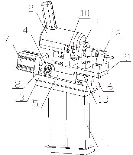
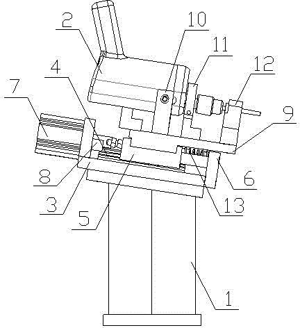
[0017] Example: see figure 2 , image 3 , an automatic drilling frame for an instrument panel beam drilling device, comprising a support frame 1 and an electric drill 2. Described bracing frame 1 top is provided with a rectangular support plate 3, is provided with a slide rail 4 along its length direction on support plate 3, slides and fits a slide block 5 on the described slide rail 4, is respectively provided at the two ends of support plate 3 There is a baffle 6, and two position-limiting columns 8 are arranged between the two ends of the slider 5 and the two baffles 6 respectively. By setting the limit column 8, the position of the electric drill can be effectively controlled during the drilling and withdrawal process, and the drilling transition and withdrawal transition can be avoided, thereby making the drilling faster and more stable.

[0018] An electric drill mounting plate is provided on the slide block 5, and the electric drill 2 is rotationally connected with t...


PUM


Abstract

The invention discloses an automatic drilling frame for an instrument panel beam drilling device. The automatic drilling frame comprises a supporting frame and an electric drill. A supporting plate is arranged on the supporting frame. A sliding rail is arranged on the supporting plate. A sliding block is arranged on the sliding rail in a sliding fit mode. The two ends of the supporting plate are each provided with a baffle. An electric drill mounting plate is arranged on the sliding block. The electric drill is in rotating connection with the electric drill mounting plate through a mounting support. An electric drill positioning frame is arranged on the electric drill mounting plate. An air cylinder is arranged on one baffle. A piston rod of the air cylinder is connected with the sliding block after penetrating through the baffle. According to the automatic drilling frame, drilling can be rapidly completed, the drilling stability is good, and therefore the drilling efficiency and quality are improved.

Description

technical field [0001] The invention relates to a processing equipment for auto parts, in particular to an automatic drilling frame for an instrument panel beam drilling device. Background technique [0002] The instrument panel crossbeam is the internal skeleton of the instrument panel system and the connecting bracket between the instrument panel system and the body assembly, which supports the instrument panel system, provides the installation of components in the instrument panel system, and increases the strength of the vehicle body. Such as figure 1 As shown, it is a tubular structure as a whole, with clamping holes (assembly holes) processed on both sides and bottom of the instrument panel beam, usually a total of 12, but due to the irregular shape of the instrument panel beam, it is usually lower at both ends and in the middle It is high and has a certain twisted structure, so it is very troublesome in the process of hole jamming. The existing processing method ad...

Claims


Application Information

Patent Timeline
Patent Type & Authority Applications(China)
IPC IPC(8): B23B41/00B23B47/22B23B49/00
CPCB25H1/0021
Inventor 唐舜清唐舜春
Owner CHONGQING HUAQING AUTOMOBILE PARTS
Why Eureka
Try Eureka