Powered pin puller

A pin puller and power technology, applied in metal processing, metal processing equipment, manufacturing tools, etc., can solve the problems of high input cost, complex structure, bulky volume, etc., and achieve the effect of reducing production cost, low price, and simple operation

Active Publication Date: 2015-03-25
NANJING CHERVON AUTOMOBILE PRECISION TECH CO LTD
View PDF6 Cites 7 Cited by
  • Summary
  • Abstract
  • Description
  • Claims
  • Application Information

AI Technical Summary

Problems solved by technology

The traditional dismantling and withdrawal process requires the use of large-scale special equipment, which is bulky and complex in structure, and the investment cost is relatively high for small enterprises
In addition, if the pin is pulled out by manual pliers, the labor intensity of the workers is high, the efficiency is low, and the workpiece will be damaged.

Method used


Image

  • Powered pin puller
  • Powered pin puller
  • Powered pin puller

Examples


Embodiment Construction

[0014] The power pin puller of the present invention will be described in detail below with reference to the accompanying drawings.

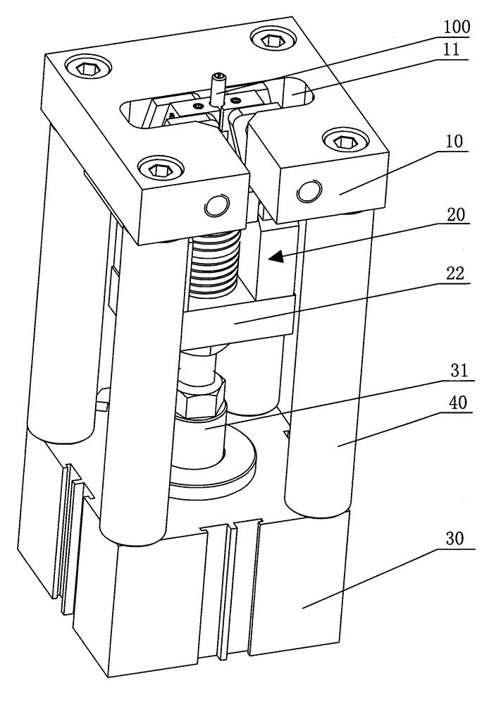
[0015] Such as figure 1 As shown, the power pin puller of the present invention includes a positioning plate 10, a sliding pin pulling device 20, and a power device 30. The sliding pin pulling device 20 is located between the positioning plate 10 and the power device 30, and the positioning plate 10 is connected by four pillars 40. on the power unit 30.

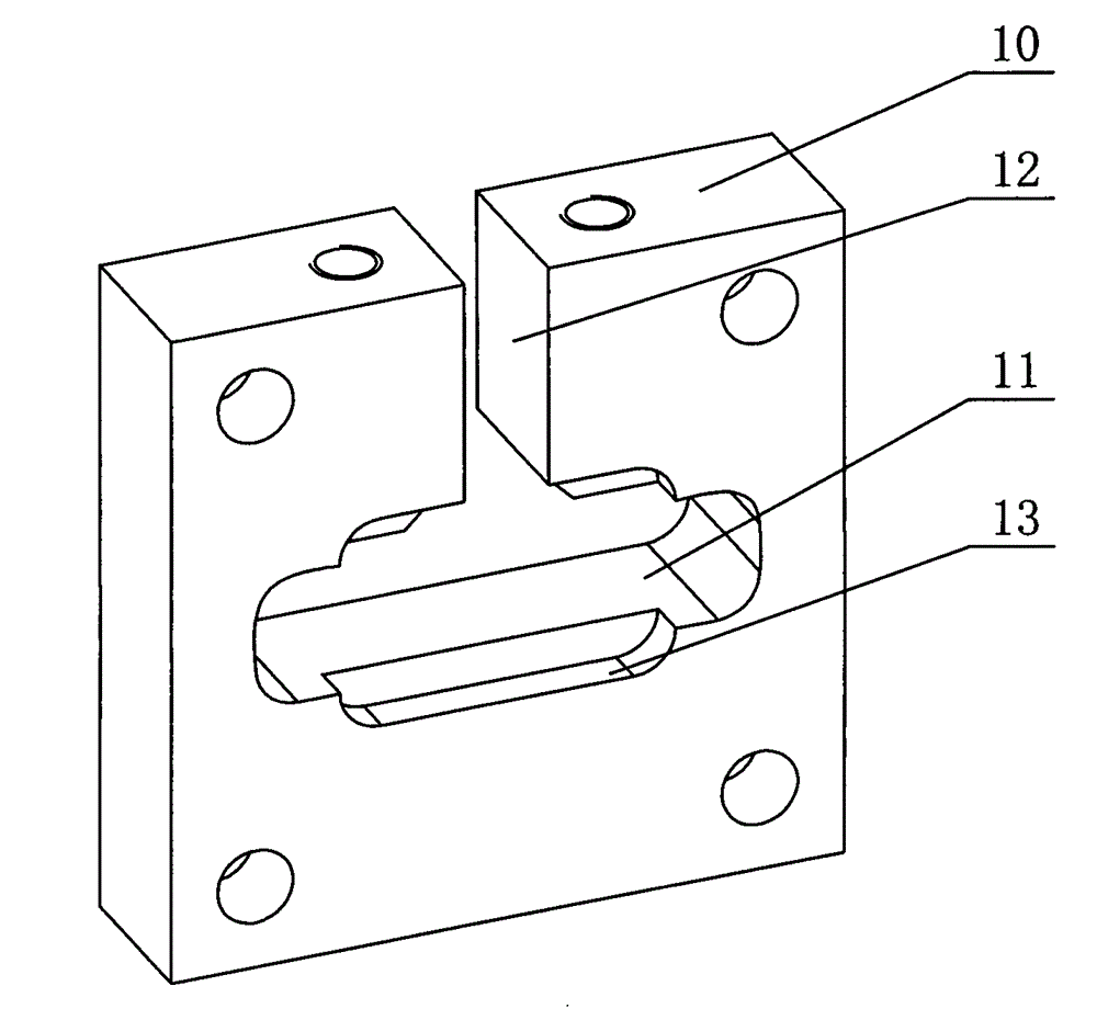
[0016] Such as figure 2 As shown, the positioning plate 10 is provided with a rectangular hole 11 and a long and narrow opening 12 , which communicate with each other. The extending direction of the opening 12 is perpendicular to the wall of the rectangular hole 11 . The rectangular hole 11 allows the positioning pin 100 to extend into the sliding pin pulling device 20 through it; the opening 12 is convenient for the operator to take out the pulled out positioning pin 100 . A pair of rectan...


PUM


Abstract

The invention discloses a powered pin puller comprising a positioning plate, a sliding pull device and a power device. The sliding pull device is disposed between the positioning plate and the power device and comprises a pull bar, a mounting plate, a pair of supports, a pair of jaws, a spring and an ejector plate; one end of the pull bar is connected with the power device; the mounting plate sleeves the pull bar; the supports are fixed on the mounting plate; each support is provided with elongated holes; the spring sleeves the pull bar over the mounting plate; the ejector plate is supported at the top end of the spring and connected between the supports; the jaws are supported on the ejector plate; a long cylindrical pin and a short cylindrical pin are fixed on each jaw and fit the elongated holes of the corresponding support; the lower surface of the positioning plate is provided with a pair of rectangular slots which limit upward movements of the long cylindrical pins. The powered pin puller is small in size, simple to operate, free of space limits and low in price and allows lower production cost for enterprises.

Description

technical field [0001] The invention relates to a power pin puller, which belongs to the field of removal tools. Background technique [0002] Locating pins play the role of locating parts in tooling and fixtures. In some cases, it is necessary to pull out the locating pins sunk in the positioning holes of parts. [0003] Taking the air-conditioning compressor cylinder block of an automobile as an example, the air-conditioning compressor cylinder block of an automobile is composed of two shells, the front cylinder and the rear cylinder, which are positioned and connected together by two serrated pins during combined processing. When the two are subjected to follow-up processing, the two need to be disassembled, and the sawtooth pin fastened in the pin hole of the rear cylinder must be pulled out. The traditional dismantling and withdrawal process requires the use of large-scale special equipment, which is bulky and complex in structure, and the investment cost is relatively...

Claims


Application Information

Patent Timeline
Patent Type & Authority Applications(China)
IPC IPC(8): B23P19/02
CPCB23P19/02B23P19/027
Inventor 储旭涛张琳邓凌曲
Owner NANJING CHERVON AUTOMOBILE PRECISION TECH CO LTD
Why Eureka
Try Eureka