Machining and locating tool of engine cylinder block
A technology for engine cylinder block and positioning tooling, which is applied to positioning devices, metal processing equipment, metal processing machinery parts, etc., can solve problems such as unstable positioning of the cylinder block, and achieve the effect of stable clamping and accurate positioning
- Summary
- Abstract
- Description
- Claims
- Application Information
AI Technical Summary
Problems solved by technology
Method used
Image

Examples
Embodiment Construction
[0012] The present invention will be described in further detail below by means of specific embodiments:
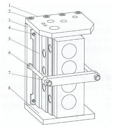
[0013] The reference signs in the accompanying drawings of the description include: upper pressing plate 1, pressing screw 2, vertical plate 3, positioning pin 4, cylinder body 5, long bolt 6, transverse pressing plate 7, lower pressing plate 8.
[0014] Examples are attached figure 1 As shown: the upper pressing plate 1 and the lower pressing plate 8 are arranged horizontally, the vertical plate 3 is arranged vertically, and four pressing screws 2 for pressing the cylinder are arranged side by side on the upper pressing plate 1, and the pressing screws 2 are close to the upper pressing plate 1 side setting. The upper platen 1 is also provided with a plurality of through holes corresponding to the surface holes of the cylinder body. On the vertical plate 3, there are two positioning pin holes along a vertical side of the vertical plate 3. The two positioning pin holes ar...
PUM
 Abstract
Description
Claims
Application Information
 - Generate Ideas
- Intellectual Property
- Life Sciences
- Materials
- Tech Scout
- Unparalleled Data Quality
- Higher Quality Content
- 60% Fewer Hallucinations
Browse by: Latest US Patents, China's latest patents, Technical Efficacy Thesaurus, Application Domain, Technology Topic, Popular Technical Reports.
© 2025 PatSnap. All rights reserved.Legal|Privacy policy|Modern Slavery Act Transparency Statement|Sitemap|About US| Contact US: help@patsnap.com