Turning clamp and application thereof

A fixture and turning technology, applied in the direction of manufacturing tools, metal processing equipment, metal processing machinery parts, etc., can solve the problems of hidden safety hazards, limited processing workpiece structure, low clamping stability, etc., to achieve accurate processing dimensions and high processing efficiency. , to ensure the effect of precision

Active Publication Date: 2015-03-25
HUBEI SANJIANG AEROSPACE HONGFENG CONTROL
View PDF9 Cites 11 Cited by
  • Summary
  • Abstract
  • Description
  • Claims
  • Application Information

AI Technical Summary

Problems solved by technology

[0006] In view of the above defects or improvement needs of the prior art, the present invention provides a turning fixture, which is used to clamp a workpiece having a circular processing element whose central axis is not parallel to the lathe spindle, so as to process the circular The element is used for turning processing. The fixture sets the optimized fixture inner cavity, and fixes the positioning block for positioning the workpiece at a certain angle in it, and adopts the optimally designed clamping parts and safety parts to realize the circular ring inclined to the central axis. The turning processing of shape processing elements solves the existing problems of limited structure of the processed workpiece, low clamping stability and potential safety hazards

Method used


Image

  • Turning clamp and application thereof
  • Turning clamp and application thereof
  • Turning clamp and application thereof

Examples


Embodiment Construction

[0038] In order to make the object, technical solution and advantages of the present invention clearer, the present invention will be further described in detail below in conjunction with the accompanying drawings and embodiments. It should be understood that the specific embodiments described here are only used to explain the present invention, not to limit the present invention. In addition, the technical features involved in the various embodiments of the present invention described below can be combined with each other as long as they do not constitute a conflict with each other.

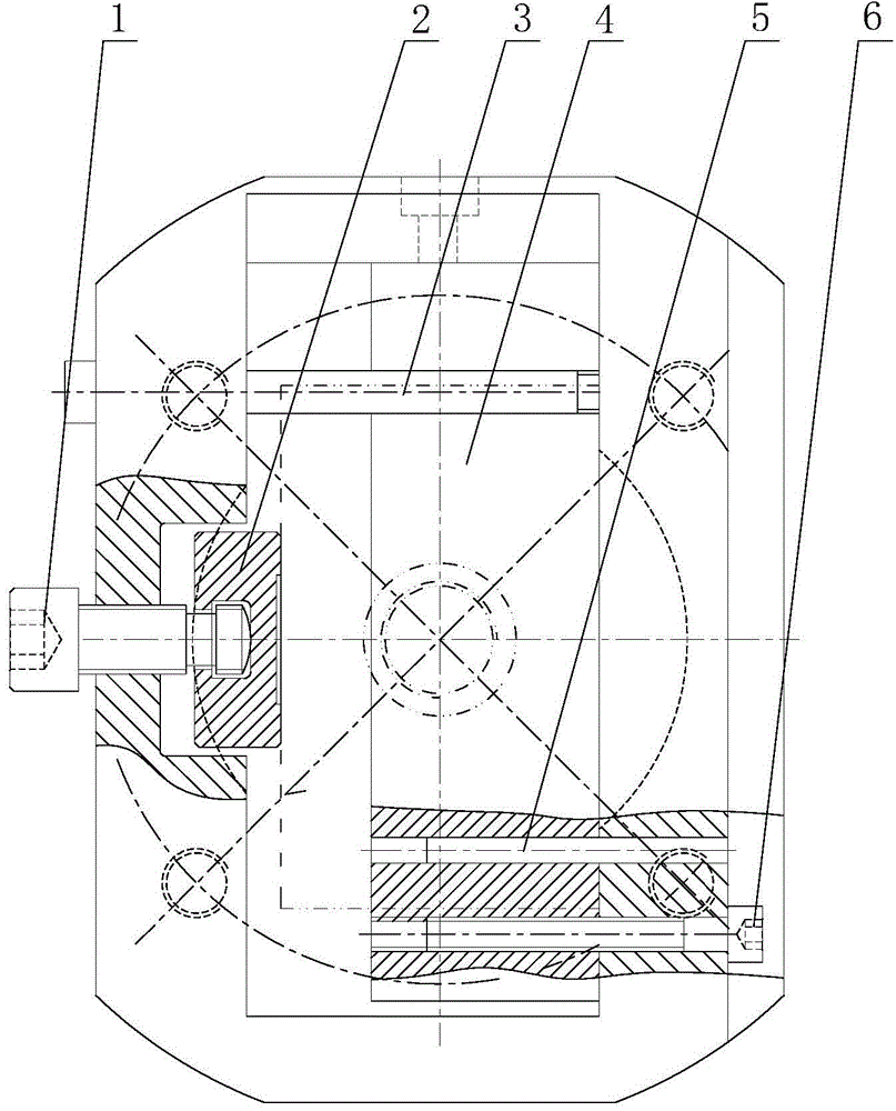
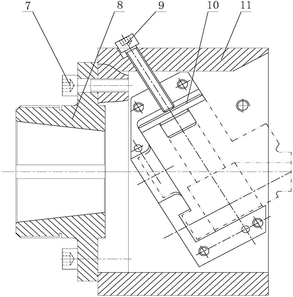
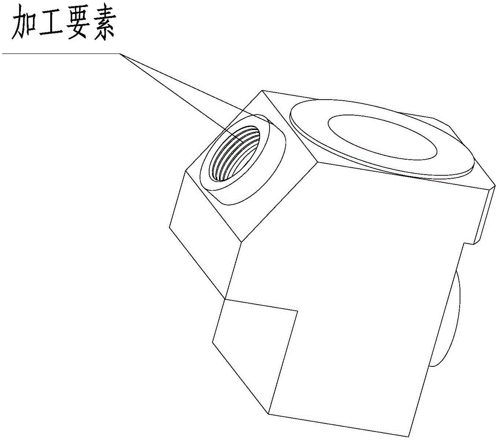
[0039] The fixture constructed according to the embodiment of the present invention is used to clamp a workpiece having a circular machining element whose central axis is not parallel to the main axis of a lathe, so as to perform turning processing on the circular machining element.

[0040] Such as figure 1 with 2 As shown, the included angle specifically includes the clamp body 11 , the pre...


PUM


Abstract

The invention discloses a turning clamp. The turning clamp comprises a clamp body, a locating block, a pressing mechanism and a safety screw, wherein the clamp body is provided with a hollow cavity, one end of the clamp body is fixedly connected with a flange plate, and the flange plate is used for being fixedly connected with a machine tool; the locating block is fixed into the cavity of the clamp body through a pin, a certain angle is formed between the locating block and the central axis of the clamp body, the locating block is provided with a locating and supporting surface which is matched with the outline of a workpiece to be machined, and after the workpiece is fixed into the locating and supporting surface, the central axis of a round-ring-shaped machined factor on the workpiece and a spindle of the machine tool coincide; the pressing mechanism comprises a first-direction pressing mechanism body and a second-direction pressing mechanism body, and the first-direction pressing mechanism body and the second-direction pressing mechanism body are used for locking the workpiece in the first direction and the second direction; the safety screw penetrates through the cavity of the clamp body and is fixed to the two opposite side faces, and the safety screw is used for preventing the workpiece in the cavity from disengaging and flying out. The invention further discloses a method of the turning clamp. By the adoption of the turning clamp and the method of the turning clamp, turning of the round-ring-shaped machined factor with the inclined central axis can be achieved, and the problems that at present, the structures of machined workpieces are limited, the clamping stability is poor, and potential safety hazards exist are solved.

Description

technical field [0001] The invention relates to the technical field of turning fixtures, in particular to a fixture for turning circular machining elements whose turning axes are inclined to the lathe spindle, such as turning of inclined cylindrical holes, circular bosses and internal and external threads. Background technique [0002] In the processing of mechanical products, sometimes inclined processing elements, such as bosses, inner holes and internal and external threads, etc., are encountered when the shape is circular, such as figure 2 The parts shown are most economical and quickest to machine by turning. However, when the axis of the circular machining element is inclined to the spindle of the lathe, the conventional lathe cannot use the three-jaw or four-jaw chuck on it for installation and positioning. [0003] However, there are two existing processing methods. One is to change to milling machine processing. The disadvantage of this method is that it needs to r...

Claims


Application Information

Patent Timeline
Patent Type & Authority Applications(China)
IPC IPC(8): B23Q3/12
CPCB23Q3/12B23Q2703/10
Inventor 涂华
Owner HUBEI SANJIANG AEROSPACE HONGFENG CONTROL
Why Eureka
Try Eureka