Special clamp for turning and drilling bent shaft with hole in the side surface

A special fixture and bending shaft technology, applied in the direction of the chuck, etc., to achieve the effects of reducing cumulative machining errors, improving machining accuracy, and increasing clamping time

Pending Publication Date: 2021-05-28
无锡迪奥数控科技有限公司
View PDF0 Cites 0 Cited by
  • Summary
  • Abstract
  • Description
  • Claims
  • Application Information

AI Technical Summary

Problems solved by technology

[0003] The invention provides a special fixture for bending shaft turning and drilling wi

Method used


Image

  • Special clamp for turning and drilling bent shaft with hole in the side surface
  • Special clamp for turning and drilling bent shaft with hole in the side surface
  • Special clamp for turning and drilling bent shaft with hole in the side surface

Examples


Embodiment Construction

[0015] In order to make the object, technical solution and advantages of the present invention clearer, the present invention will be further described in detail below in conjunction with the accompanying drawings and embodiments. It should be understood that the specific embodiments described here are only used to explain the present invention, not to limit the present invention.

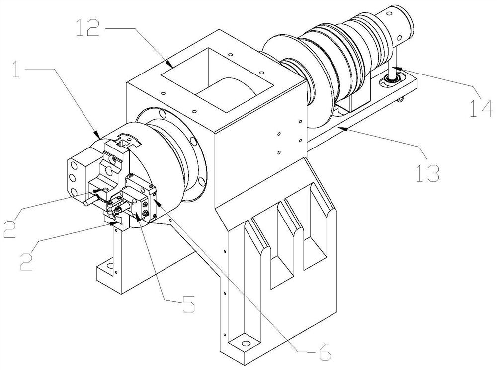
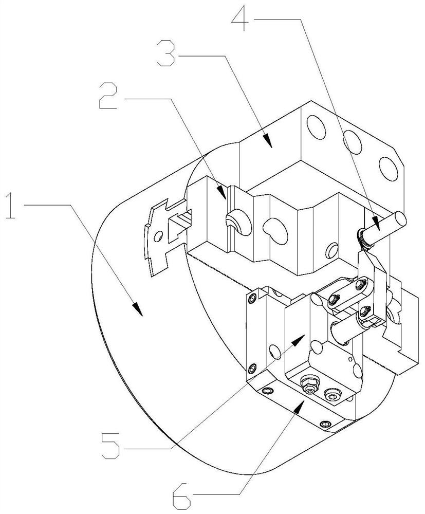
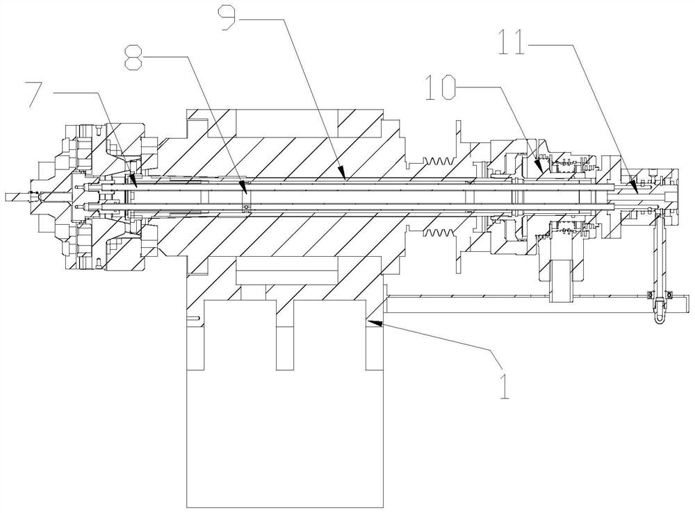
[0016] see Figure 1-3 , the present invention provides a technical solution: a special fixture for bending axis turning and drilling with holes on the side, including a spindle box 12 and a chuck body 1 installed thereon; a pair of The claws 2 that can hold the workpiece 4, and the claws 2 can cooperate with each other after relative movement to clamp the outer diameter of the workpiece 4;

[0017] A clamping hydraulic cylinder 5 with a clamping portion is also installed on the chuck body 1, and the output shaft of the clamping hydraulic cylinder 5 can drive the clamping portion to move, thereby ...


PUM


Abstract

The invention is applicable to the technical field of mechanical equipment, and provides a special clamp for turning and drilling a bent shaft with a hole in the side surface. The special clamp comprises a spindle box and a chuck body mounted on the spindle box. A pair of clamping jaws capable of clamping a workpiece are oppositely arranged on the chuck body, and the clamping jaws can move relatively and then are matched with each other so as to clamp the outer diameter of the workpiece. A clamping hydraulic cylinder with a clamping part is further mounted on the chuck body, and an output shaft of the clamping hydraulic cylinder can drive the clamping part to move, so that the outer edge of the side part of the workpiece is clamped. The clamping jaw clamps the workpiece in the diameter direction, turning of a common machine tool is achieved, the clamping hydraulic cylinder clamps the outer edge of the side position of the workpiece needing to be machined, clamping force is provided for side position machining, machining procedures are reduced, machining cost is reduced, accumulated machining errors are reduced, machining precision is improved, machining time and clamping time are shortened, and machining efficiency is improved.

Description

technical field [0001] The invention belongs to the technical field of mechanical equipment, and in particular relates to a special fixture for turning and drilling of bent shafts with holes on the side. Background technique [0002] When the workpiece needs to be turned and side hole processed, ordinary lathes cannot be used to complete the processing at one time. Usually, the process design of turning and drilling is separated, or a corresponding special machine is designed for processing, or multi-axis processing equipment such as a machining center is used for processing. Both solutions increase production costs. Contents of the invention [0003] The invention provides a special fixture for turning and drilling of bent axis with holes on the side, aiming to solve the problems mentioned in the background technology. [0004] The present invention is achieved in this way, a special fixture for bending shaft turning and drilling with holes on the side, including a spind...

Claims


Application Information

Patent Timeline
IPC IPC(8): B23B31/12B23B31/30
CPCB23B31/12B23B31/302
Inventor 陈立如
Owner 无锡迪奥数控科技有限公司
Why Eureka
Try Eureka