A rear anti-collision beam assembly suitable for various automobiles

A technology for cross beam assembly and rear collision avoidance, which is applied in vehicle components, vehicle safety arrangements, bumpers, etc., can solve the problems that the stamping depth cannot be widely used, increase the development cost, and affect the drawing rate, so as to reduce the number of tooling and Management cost, easy and reliable installation, high strength effect

Active Publication Date: 2017-05-03
CHONGQING CHANGAN AUTOMOBILE CO LTD
View PDF1 Cites 0 Cited by
  • Summary
  • Abstract
  • Description
  • Claims
  • Application Information

AI Technical Summary

Problems solved by technology

Although the strength of the bowl-shaped mounting bracket can be improved, due to the influence of the elongation rate of the material, the stamping depth is limited and cannot be widely used. It is in a dilemma that the stamping depth and material selection of the bracket are limited, and two symmetrical installations need to be made on the left and right. Double the number of brackets b, c, molds and inspection tools, which is not conducive to cost optimization;
[0004] (2) Due to the different shapes of cars, the width and rear space of different models are limited by the shape. Even if the rear collision beam assembly of a general car can meet the collision requirements of other models, it cannot be used on models of different widths due to the limited location of the installation point. Increased development costs;
[0005] (3) During assembly, in order to reduce the labor intensity of workers and ensure smooth assembly, it is necessary to achieve preliminary positioning of the guide pin d on the left and right mounting brackets, resulting in increased tooling costs and costs
But it doesn't solve the problem of generality

Method used


Image

  • A rear anti-collision beam assembly suitable for various automobiles
  • A rear anti-collision beam assembly suitable for various automobiles
  • A rear anti-collision beam assembly suitable for various automobiles

Examples


Embodiment Construction

[0025] The present invention will be further described below in conjunction with the accompanying drawings.

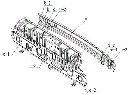
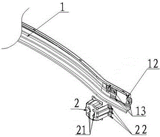
[0026] see figure 2 , image 3 , Figure 4 and Figure 5 , shows a rear anti-collision beam assembly suitable for automobiles, including an exterior panel 1, and mounting brackets 2 respectively connected to the two ends of the exterior panel. Its outstanding substantive features are:

[0027] One end of the profile plate 1 is provided with a process square hole 12, and a first lap surface 13 is provided on the edge close to the process square hole. The structure of the parts is the same and symmetrical to each other;

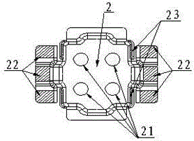
[0028] The mounting bracket 2 is in the shape of an open square box, and the four sides of the mouth are provided with flanging, and are distributed symmetrically with its center, wherein the left and right symmetrical flanging are divided into three second lap joints by two reinforcing ribs respectively. Surface 22, the two sides of the up and do...


PUM


Abstract

The invention relates to a rear anti-collision beam assembly suitable for multiple automobiles. The rear anti-collision beam assembly comprises an exterior board and installation supports. A square auxiliary hole is formed in one end of the exterior board, a first lap joint surface is arranged close to the edge of the square auxiliary hole, and the structure of the other end of the exterior board is the same as that of one end of the exterior board. Each installation support is of an open square box shape, and folded edges are arranged on the four sides of each opening portion and distributed symmetrical about the center of the opening portion, wherein the two laterally-symmetrical folded edges are spaced into three second lap joint surfaces through two reinforcing ribs, the two sides of the two vertically-symmetrical folded edges are provided with small planes connected with the left side wall and the right side wall of the square box shape, multiple installation holes are formed in the bottom of the square box shape, and the installation supports are correspondingly connected with the first lap joint surface at the edge of the square auxiliary hole in the exterior board. The left installation support and the right installation support can be interchanged and used, the positions of the installation supports can be adjusted, the installation supports are matched with different automobile types by changing the distance between installation points, and universality is high.

Description

technical field [0001] The invention belongs to automobile body components, in particular to a rear anti-collision beam assembly suitable for various automobiles. Background technique [0002] The rear anti-collision beam of the car is located between the rear apron and the rear bumper, and is generally connected to the rear apron by bolts. The safety of low-speed collisions of automobiles is a mandatory regulatory requirement, and domestic regulations require collisions to meet the requirements of the national standard "Safety Requirements for Passenger Car Rear Collision Fuel System" (GB20072-2006). With the continuous development of the automobile industry, the requirements for the safety performance of cars are getting higher and higher, and the laws and regulations of various countries are gradually improving. Therefore, it is very necessary to install rear anti-collision beams at the rear of the car body to ensure the safety of passengers and property. At present, dif...

Claims


Application Information

Patent Timeline
Patent Type & Authority Patents(China)
IPC IPC(8): B60R19/02
CPCB60R19/24B60R2019/247
Inventor 王凯剑曹杰朱峰吴迪廖水平
Owner CHONGQING CHANGAN AUTOMOBILE CO LTD
Why Eureka
Try Eureka