Al technical title is built by PatSnap Al team. It summarizes the technical point description of the patent document.
A thruster and piezoelectric technology, which is applied to the propulsion system of space navigation vehicles, etc., can solve the problems of long response time, short life and unadjustable thrust, and achieve the effect of fast response speed, good sealing performance and good sealing performance.
Inactive Publication Date: 2016-04-06
NAT UNIV OF DEFENSE TECH
View PDF7 Cites 0 Cited by
Summary
Abstract
Description
Claims
Application Information
AI Technical Summary
This helps you quickly interpret patents by identifying the three key elements:
Problems solved by technology
Method used
Benefits of technology
Problems solved by technology
The purpose of the present invention is to provide a piezoelectric driven micro thruster to meet the needs of micro satellites and missiles for precision orbit determination on micro thrusters. Strict requirements for propulsion systems
Method used
Image
Click on the blue label to locate the original text in one second.
Reading with bidirectional positioning of images and text.
Examples
Embodiment Construction
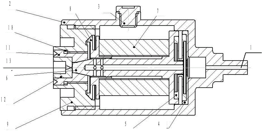
[0027] The piezoelectric micro thruster of the present invention will be further described below in conjunction with the working principle and the accompanying drawings. It should be noted here that the descriptions of these embodiments are used to help understand the present invention, but are not intended to limit the present invention.
[0028] The piezoelectric drive device utilizes the deformation characteristics of the piezoelectric stack under the action of an electric field, and combines the action of the return spring and the washer spring to push the T-shaped valve core to move to realize the switch function of the thruster. The working principle of the piezoelectric micro thruster of the present invention is as follows: under a given voltage, the piezoelectric stack will increase the micro scale along the axial direction of the micro thruster, push the valve core to move towards the air inlet, and squeeze the reset spring and The gasket spring deforms it. At this ti...
PUM
Abstract
The invention provides a piezoelectric micro-thruster comprising an air inlet (1), a housing (2), a power interface (3), a filter (4), a return spring (5), a valve core (6), a piezoelectric stack (7), a washer spring (8), a valve seat (9), a seal ring (10), an adjusting ring (11), a base (12) and a nozzle (13). In the case of power-off, the surface of the valve core (6) is tightly attached to the surface of the valve seat (9) and the surface of the adjusting ring (11), and the piezoelectric micro-thruster is off; in the case of power-on, the piezoelectric stack (7) deforms to drive the valve core (6) to move, the surface of the valve core (6) separates from the surface of the valve seat (9) and the surface of the adjusting ring (11), the piezoelectric micro-thruster is on and generates thrust. The sealing parts, such as the valve core (6), the valve seat (9) and the adjusting ring (11), are all made of metal, thus the piezoelectric micro-thruster is metal sealed. The piezoelectric micro-thruster is short in response time, continuously adjustable in thrust, low in power consumption and long service, meets the strict requirements of miniature satellites and missile precision guides for micro-thrust systems and is light in weight and small in size, and more weight and space are saved for the miniature satellites.
Description
technical field [0001] The invention belongs to the technical field of spacecraft propulsion systems, in particular to a piezoelectric micro thruster. Background technique [0002] The existing micro thrusters are all driven by electromagnetic, and their working principle is as follows: when the voltage is input, the electromagnetic coil generates force, attracts the valve body, makes it leave the valve seat, opens the gas flow path, and the gas enters from the air inlet and flows through the valve body. The fixed gas flow path is finally ejected from the nozzle to realize the propulsion process; when the power is cut off, the force of the electromagnetic coil disappears, and the valve body returns to the valve seat under the spring’s rebound force, closing the gas flow path, and the propulsion process End. In the existing micro thrusters, the solenoid valve acts as a latch to open and close the gas flow path. The size and path of the gas flow path are fixed, so when the fl...
Claims
Application Information
Patent Timeline
Application Date:The date an application was filed.
Publication Date:The date a patent or application was officially published.
First Publication Date:The earliest publication date of a patent with the same application number.
Issue Date:Publication date of the patent grant document.
PCT Entry Date:The Entry date of PCT National Phase.
Estimated Expiry Date:The statutory expiry date of a patent right according to the Patent Law, and it is the longest term of protection that the patent right can achieve without the termination of the patent right due to other reasons(Term extension factor has been taken into account ).
Invalid Date:Actual expiry date is based on effective date or publication date of legal transaction data of invalid patent.